33
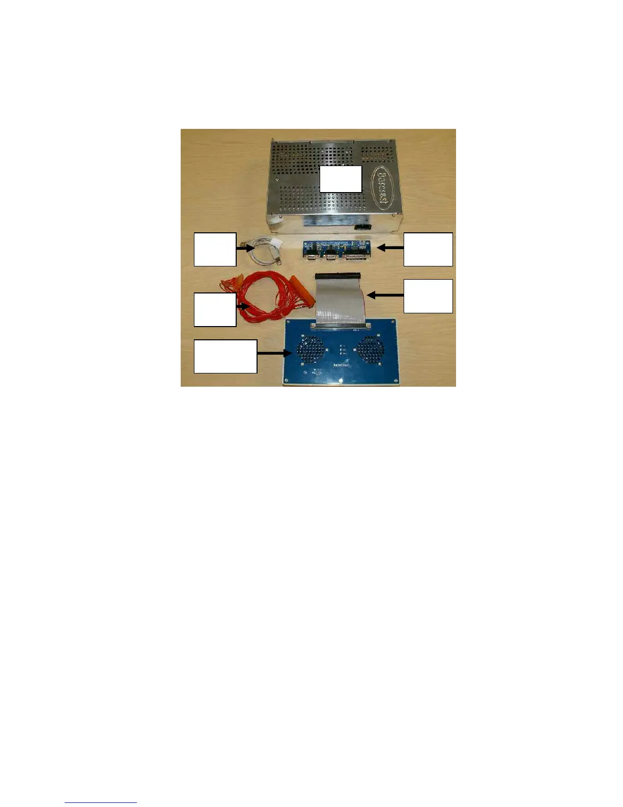
3.5.3 MPU6 Test Jig Main Components.
The image below shows the main components of the MPU6 test jig assembly.
3.5.4 Overview
The functional testing of the MPU6 system board is carried out using a special purpose test
jig to carry out testing of on-board interfaces, switches communications facilities including the
central processor.
The MPU6 is provided with its own internal test routine software to work specifically with the
test panel to enable a functionality test. The kit is shown in the image below with the main
components connected.
The test jig assembly consists of a MPU6 test panel containing two speakers and three LED
voltage indicators to represent 13V and two 24V supplies connected via a ribbon cable to the
MPU6 64-way connector.
Barbus
PSU