60
4.21 LED displays
The MUX5 board can drive up to eight LED displays, each comprising seven segments plus
a decimal point.
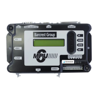
4.22 Alphanumeric display
Provision to drive an Alphanumeric Display is made through a black 7-way ALPHA connector
on the MUX5(E) board, having a keyway at pin position 5. A simple jumper harness links
through to a connector on the display PCB.
The interface signals being at TTL levels. Data (ALPHA_DATA) is fed from the CPU to the
display serially in synchronism with a clock signal ALPHA_CLK, at variable rates up to
approximately 100kbits/sec. The DUART outputs are protected by Zener diodes against
possible +12V under fault conditions.
Before initialisation takes place it is quite normal to have random characters shown on the
display, so a reset signal ALPHA_RES is used during initialisation to blank the display.
4.23 Status indication
The status indicator displays a flashing Green LED when it is in normal operation. In the
event of a fault then one of the following LED Codes will help to diagnose the fault on the
PCB.
• The enable transistors are tested. If they fail the status LED flashes 3 Red 1 Green.
• The drive transistors are tested. If they fail the status LED flashes 2 Red 1 Green.
• The comms buffer is tested. If it fails the status LED flashes 1 Red 1 Green.
4.23.1 +37V Status LED
The +37V supply rail is monitored by an LED which glows green to show a healthy supply.
On power-up a bi-colour Status LED glows red, then green, then off, then flickers green to
indicate comms activity. At the end of a message the LED glows steady green.
4.23.2 Communications
A bi-colour STATUS red/green LED is located adjacent to the processor. The LED indicates
as follows:
• On power up the LED shows red, then green and then off, then flickers green to show
data is being received. At the end of a message the LED shows green for a brief
period until the next message begins.
• If there is a fault at power up, the LED shows red.
• If the LED remains extinguished, there is no communication with the MPU5 board.
This could be due to power failure (e.g. 12V fuse).