65-8 9424200996
Inverse Overcurrent (51) Test BE1-11m
Step 6: (Optional.) Repeat steps 1 through 5 for settings group 1, 2, and 3.
Step 7: (Optional.) Repeat steps 1 through 6 for 51-2, 51-3, 51-4, and 51-5.
Step 8: (Optional.) Repeat steps 1 through 7 with CT Circuit 2 as the source for protection systems
equipped with two sets of CTs. In step 3, replace D1 with F1, D2 with F2, etc.
Pickup Verification (IG Mode)
Step 1: Use BESTCOMSPlus to send the operational settings in Table 65-13 to the BE1-11m. Reset all
targets.
Table 65-13. Operational Settings (IG Mode)
System Parameters, Sensing
Transformers
Sets ground CT ratio to 1
Protection, Current, Instantaneous
Overcurrent (51-1)
Enables 51-1 function for
IG mode
Protection, Current, Instantaneous
Overcurrent (51-1)
Selects CT circuit 1 as the
source
Target Configuration, Targets
Enables IND GND target
for 51-1
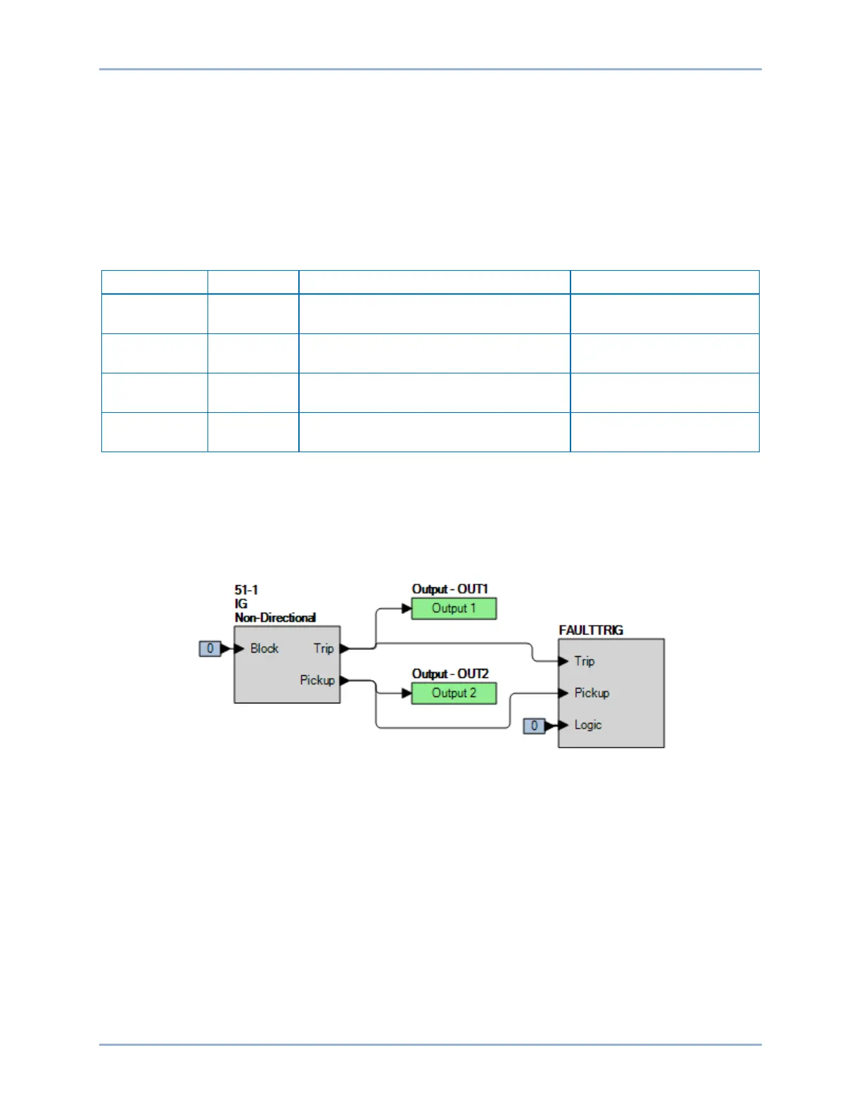
Step 2: Use BESTCOMSPlus to configure the BESTlogicPlus programmable logic shown in Figure
65-4.
• Blocking is disabled.
• OUT1 closes for 51-1 Trip.
• OUT2 closes for 51-1 Pickup.
• Fault recording is enabled.
Figure 65-4. BESTlogicPlus Settings (IG Mode)
Step 3: Use BESTCOMSPlus to open the Protection, Current, Inverse Overcurrent (51-1) screen and
send the low range test settings (minimum pickup setting) to the BE1-11m for your sensing input
type in Table 65-14.
Step 4: Prepare to monitor the 51-1 function operation. Operation can be verified by monitoring OUT2
(see Figure 65-4).
Step 5: Connect a current source to terminals D7 and D8 (IG).
Step 6: Slowly increase the ground current until OUT2 closes and record the pickup. Verify that there is
a 51-1-IND GND target on the front-panel display. Slowly decrease the applied current until
OUT2 opens and record the dropout.
Step 7: Repeat step 6 for the middle and high range pickup settings for your sensing input type. Record
the results.
Step 8: (Optional.) Repeat steps 1 through 7 for settings group 1, 2, and 3.
Step 9: (Optional.) Repeat steps 1 through 8 for 51-2, 51-3, 51-4, and 51-5.