12
Basic FBM CPU
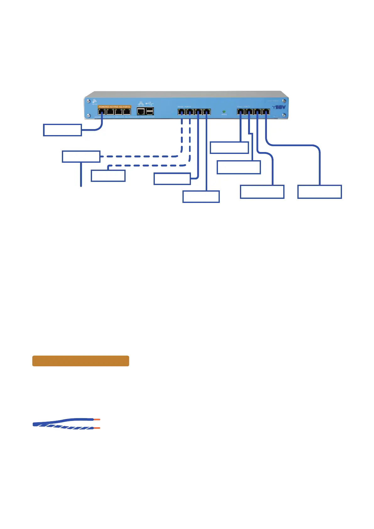
The CPU is the main controller for the system, for which the connector details are shown below:
CPU 4
Network 10 / 100 Port 192.168.0.63 Interconnection with Matrix Switch
WIFI Access Point BBV_AP 192.168.42.1 Password: BBVCCTV111
BBV Quad USB to Serial Interfaces
Network USB2 Interconnection with the CPU
Com A Keypad or BBUS interface addresses 0 to 7 (keypads 1 to 8)
Com B Alarms 1 - 128
Com C Telemetry Port (Pelco-D 9600 8 N 1)
Com D Telemetry Port (Pelco-D 9600 8 N 1)
Port E Key 9-16
Port F Alarms 129 - 255
Port G Telemetry
Port H Telemetry
Alarms
USB
System Component Details
Alarm
Telemetry 3
Telemetry 4
Telemetry 1
Telemetry 2
RJ45 Telemetry Connections (Blue Pair)
Tx+ Blue
Tx- Blue & White
Keypads 1-8
Keypad
4x powered keypad ports
Daisy chain port
Keypads 9-16
POWERED KEYPAD 422 PORTS
4 Ports for keypads which mirror Port A, with power. Good for 100 metres of Cat5 cable. Make sure the keypads are
addressed correctly (see page 17).