EasyManua.ls Logo

BEA LZR-MICROSCAN T - User Manual

BEA LZR-MICROSCAN T
16 pages
Print Icon
To Next Page IconTo Next Page
Loading...
75.5753.15 LZR-MICROSCAN T 20180720 Page 1 of 16
LZR-MICROSCAN T
2
1
3
5
4
8
9
6
7
Stand-Alone, Door-Mounted, Safety Sensor System
for Automatic Swing Doors* (US version)
* LZR-microscan sensors are intended to be used
with pedestrian, swing-door systems.
75.5753.15 LZR-MICROSCAN T 20180720 Page 1 of 16
ENGLISH
DESCRIPTION
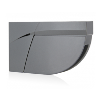
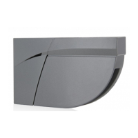
1. tilt adjustment 4. endcaps 7. adjustment knob
2. sensor connection ports 5. optical window 8. LCD
3. sensor LED 6. plug-n-play ports 9. hub LEDs
INCLUDED KIT COMPONENTS
DESCRIPTION PART NUMBER SINGLE PAIR/DE
Left LZR-microscan T Sensor 10LZRMICROLEFTT 1 2
Right LZR-microscan T Sensor 10LZRMICRORIGHTT 1 2
LZR-microscan T Hub 10LZRMICROSCANHUBT 1 1
Master Sensor Harness 35.1326 1 2
Slave Sensor Harness 35.1327 1 2
Door Control Harness 20.5222 1 2
System Harness 20.5304 1 1
Eagle Harness 20.5096 2 2
Power Supply Harness 20.5095 1 1
Home Switch (Surface Mount) 50.5283 1 2
Door Loop / Cap Kit 70.0202 / 50.0078 1 2
On / Off / Hold Open Switch Jumper 20.5310 1 1
Left Pass-Through Sensor Endcap 41.7922 1 2
Right Pass-Through Sensor Endcap 41.7923 1 2
Sensor Spacer 70.5554 1 2
Spacer Mount Screws (Metal) 50.0048 2 4
Spacer Mount Screws (Wood) 50.5319 2 4
Sensor Mount Screws (Metal) 50.1818 4 8
Sensor Mount Scews (Wood) 50.5282 4 8
Endcap Screws 41.8632 4 4
Velcro Tabs 50.0046 2 2
LZR-microscan T Mounting Template 75.5754 1 1
LZR-microscan T User’s Guide 75.5753 1 1
LZR-microscan T Wiring Tech Bulletin 78.0053 1 1
Universal Kit
(Power Supply - 30.5558, On / Off /
Hold Open Switch - 10DOORSWITCH)
10MICROSCAN-UKIT
1 (Universal Kit ONLY) 1 (Universal Kit ONLY)
REQUIRED TOOLS
TOOL
Power Drill
Tape Measure
Magnetic Phillips #0
Phillips #2
1
⁄
8
” Drill Bit
5
⁄
16
” Drill Bit
3
⁄
8
” Drill Bit
1
⁄
2
” Drill Bit
Pencil
Center Punch / Hammer
Wire Nuts
Wire Snips
Wire Fish
KITS
DESCRIPTION PART NUMBER
Single Door
10LZRMICROSCAN1T
Pair / Dual-Egress
Door
10LZRMICROSCAN2T
Universal Single
Door
10LZRMICROSCAN1UT
Universal Pair /
Dual-Egress Door
10LZRMICROSCAN2UT
Narrow-Frame Door
10MICROSCANMOUNTT
Glass/Fire Door 10MICROSCAN-Y
Universal Kit 10MICROSCAN-UKIT

Other manuals for BEA LZR-MICROSCAN T

Questions and Answers

  • S
    Sherry SchmidtSep 1, 2025
    How to fix Hub Environment error in BEA LZR-MICROSCAN T Security Sensors?
    • B
      Brian ThompsonSep 1, 2025
      To resolve a Hub Environment error on BEA Security Sensors, verify the power supply voltage and ensure you are using a BEA power supply. Also, ensure that the environment temperature is within the operational range for the hub.
  • S
    Samantha WilliamsSep 2, 2025
    How to resolve Boundary error in BEA LZR-MICROSCAN T Security Sensors?
    • J
      John CampbellSep 2, 2025
      To fix a Boundary error in BEA Security Sensors, install spacers and perform a new “teach-in.” Also, tighten the sensor tilt angle screw and trim the transfer loop, then perform a new “teach-in.”
  • R
    Renee LewisSep 3, 2025
    How to fix BEA LZR-MICROSCAN T Hub LCD if it is not on?
    • D
      David VargasSep 3, 2025
      If the Hub LCD is not on for BEA Security Sensors, verify the power supply connection and ensure the power supply is functioning correctly, preferably using a BEA power supply. If the issue persists, the hub may be faulty and needs replacement.
  • K
    Kelly KaneSep 4, 2025
    Why Visible Monitoring indication LED does not flash on BEA LZR-MICROSCAN T?
    • J
      jonessaraSep 4, 2025
      If the Visible Monitoring indication LED does not flash on BEA Security Sensors, verify that the door control is capable of monitoring and that the sensor monitoring wires are properly connected to the door control. Also, verify the wiring for any breaks. If the issue remains, replace the sensor.
  • R
    Randy GarciaSep 4, 2025
    What to do if BEA Security Sensors display Cap LCD screen?
    • S
      Steven ClarkeSep 5, 2025
      If the BEA Security Sensors display a Cap LCD screen, perform a re-Teach-in.
  • A
    amber78Sep 5, 2025
    How to fix EDPS “teach-in” error on BEA LZR-MICROSCAN T Security Sensors?
    • E
      elizabethjonesSep 5, 2025
      To resolve an EDPS “teach-in” error (2nd most common) on BEA Security Sensors, ensure that the switch is set to ON and wired correctly. Adjust the door(s) to open at least 80°, increase the door opening speed to 9 seconds or less, and adjust the home switch as needed. If the problem persists, the sensor gyro may be bad, and the sensor should be replaced.
  • C
    Cathy MaysSep 6, 2025
    How to fix 'Height/Angle Error' on BEA LZR-MICROSCAN T Security Sensors?
    • E
      Elizabeth McfarlandSep 6, 2025
      To address a 'Height/Angle Error: No floor recognized' issue with BEA Security Sensors, check the mounting height and angle against the template. If a transfer loop is present, ensure it is trimmed and not hanging under the sensor. Also, verify the sensors are handed correctly for the mounting location (i.e. Left Mount / Right Mount). If the sensor is detecting door hardware, tighten the tilt adjustment screw and install LZR spacers if necessary.

Summary

DESCRIPTION

PRECAUTIONS

LASER

INSTALLATION

MAINTENANCE

SAFETY

HOW TO USE THE LCD

Display During Normal Operation

Shows different display modes and their meanings during normal operation.

Factory Value vs. Saved Value

Explains the difference between factory default and user-saved parameter values.

Navigating in Menus

Step-by-step guide to navigating the LCD menus using buttons.

Changing a Value

Process for selecting and changing parameter values using the adjustment knob.

LED Status

Explains the color and signal meanings of the Hub and Sensor LEDs.

PREPARATION

Hub

Instructions for installing the hub in the door header, ensuring accessibility.

Sensors

Guidance on determining sensor handedness and mounting it on the door loop side.

INSTALLATION (cont.)

Sensors

Using the template to position sensors, mark holes, and drill for accurate mounting.

INSTALLATION (cont.)

Peripherals

Instructions for installing and wiring the Home Switch for door status indication.

Home Switch

Instructions for installing and wiring the Home Switch for door status indication.

On;Off; Hold Open Switch

Mounting and wiring the On/Off/Hold Open switch and understanding jumper wire functions.

INSTALLATION (cont.)

Eagle (optional)

Instructions for installing optional Eagle sensors and push plates.

Push Plates (optional)

Instructions for installing optional Eagle sensors and push plates.

Door Control Harness

Connecting the Door Control Harness for independent door controls and dual-egress systems.

WIRING

Power

Instructions for connecting the power supply to the hub and wiring to a power source.

External Monitoring

How to use monitoring wires for external system status checks.

SET-UP

OVERVIEW OF SETTINGS

Menu 1 (BASIC)

Details basic parameters like Door Type, Detection Zone, and Guiderail settings.

Menu 2 (ADVANCED)

Explains advanced settings such as Monitoring, KnowingAct, and AdvanceSafe options.

OVERVIEW OF SETTINGS (cont.)

Menu 3 (DIAGNOSTICS)

How to view door status, active devices, and system parameters through diagnostic menus.

TROUBLESHOOTING

General

Solutions for common issues like no hub LCD, no clear area, or sensor errors.

TROUBLESHOOTING (cont.)

Set-up Errors

Covers errors like incorrect mounting height, angle, or sensor visibility during setup.

TROUBLESHOOTING (cont.)

Runtime Errors

Solutions for boundary errors, environmental factors, and communication loss.

TROUBLESHOOTING (cont.)

Orange LED (Sensor) Errors

Explains errors indicating internal or external faults, power supply, or temperature issues.

TECHNICAL SPECIFICATIONS

BEA INSTALLATION;SERVICE COMPLIANCE EXPECTATIONS

Notes on installer qualifications, safety inspections, and compliance with standards.

BEA LZR-MICROSCAN T Specifications

General IconGeneral
BrandBEA
ModelLZR-MICROSCAN T
CategorySecurity Sensors
LanguageEnglish

Related product manuals