Commissioning
EL3773 87Version: 2.5
Data processing
The data processing is done simultaneously for all channels in the EL3773 with 16-bit conversion in the ADC
Scaling related to the respective (constant) measuring range:
1. Vendor calibration (0x80p0:0B [
}
95])
Activation: CoE 0x80p0:0B
X
1
= (X
ADC
- Offset
Vendor
) * Gain
Vendor
This produces the following signed integer value representation:
Input signal Value
Voltage Current Decimal Hexadecimal
410V 1.5A 32767 0x7FFF
205V 0.75A 16383 0x3FFF
0V 0A 0 0x0000
-205V -0.75A -16383 0xC001
-410V -1.5 A -32767 0x8000
Signed integer: the negative output value is represented in two’s complement (negated + 1). Maximum
representation range for 16 bits = -32768 to +32767
dec
.
2. User calibration (0x80p0:0A [
}
95])
Activation: CoE 0x80n0:0A
X
2
= (X
1
- Offset
User
) * Gain
User
3. Limit value evaluation (0x80p0:13 [
}
95], 0x80p0:14 [
}
95])
Display in the status word [}91] of the channel
If the value exceeds or falls below these values, which can be entered in the indices 0x80p0:13 [}95] and
0x80p0:14 [}95], then the bits in the indices 0x60p0:03 [}96] and 0x60p0:05 [}96]are set accordingly
(see example [}87] below).
The entry 0x80p0:07 [}95] serves to activate the limit value monitoring.
Output limit n (2-bit):
• 0: not active
• 1: One or more values <= Limit n
• 2: One or more values >= Limit n
• 3: Cases 1 and 2 simultaneously
Note
Linking in the PLC with 2-bit values
The limit information consists of 2 bits. Limitn can be linked to the PLC or a task in the Sys-
tem Manager:
• PLC:
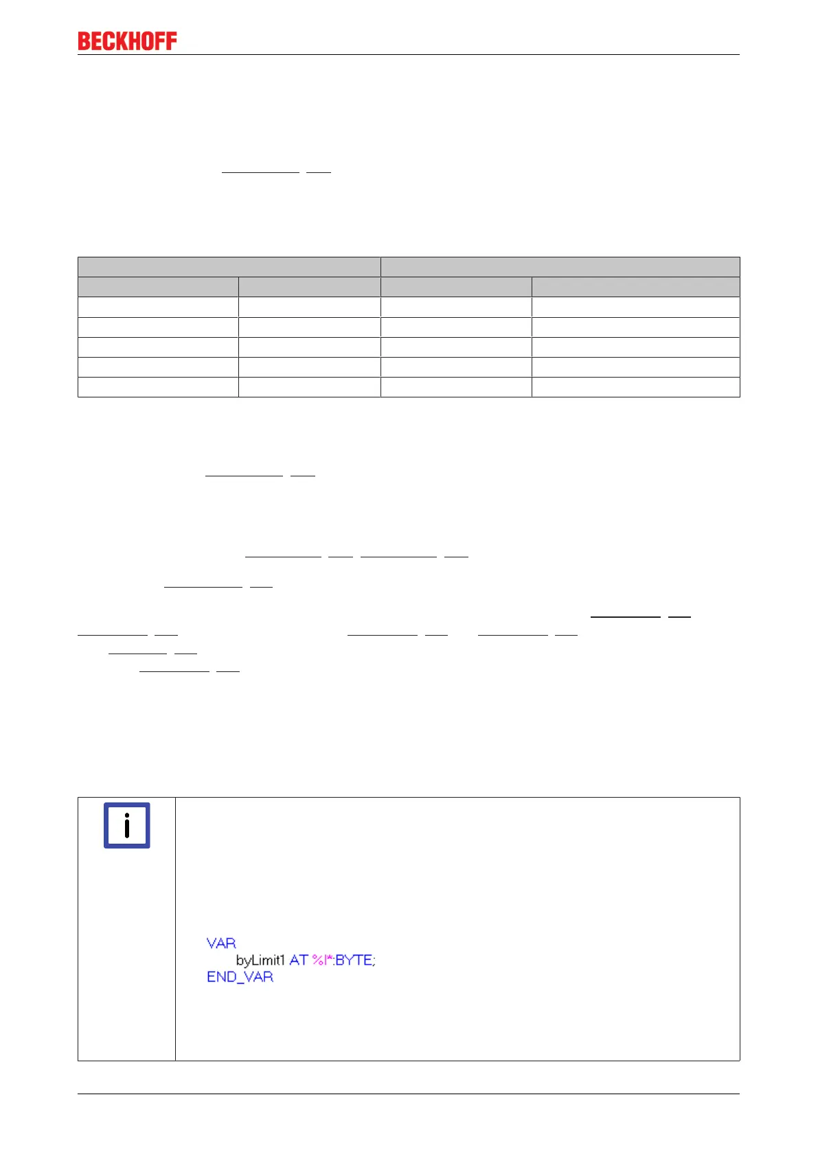
IEC61131-PLC contains no 2-bit data type that can be linked with this process data di-
rectly. In order to transmit the limit information, therefore, define an input byte, e.g.
and link the limit with the VariableSizeMismatch dialog.
• Additional task
2-bit variables can be created in the System Manager.