Commissioning
EL70x1192 Version: 4.4
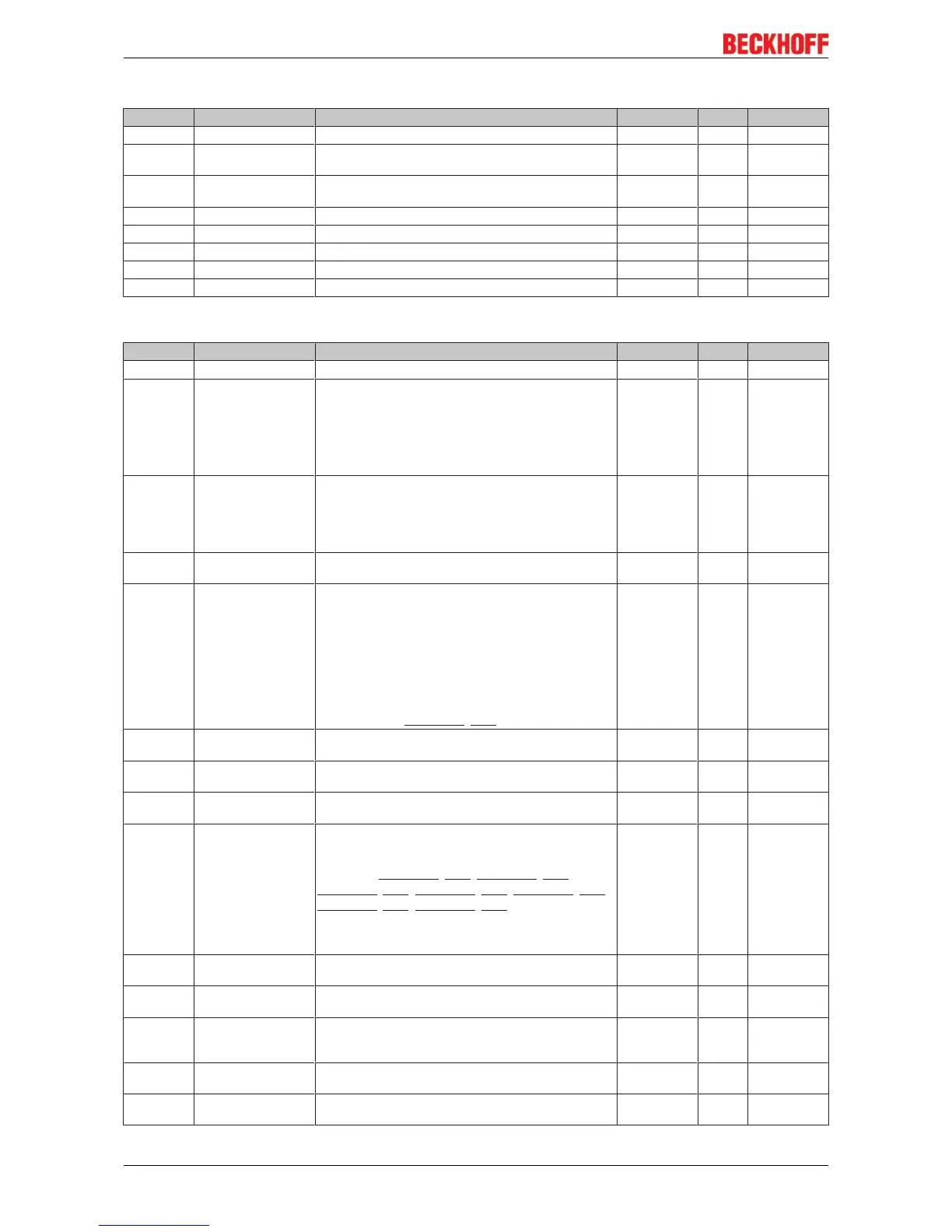
Index 1C13 TxPDO assign
Index (hex) Name Meaning Data type Flags Default
1C13:0 TxPDO assign PDO Assign Inputs UINT8 RW 0x02 (2
dec
)
1C13:01 Subindex 001 1. allocated TxPDO (contains the index of the associated
TxPDO mapping object)
UINT16 RW 0x1A00
(6656
dec
)
1C13:02 Subindex 002 2. allocated TxPDO (contains the index of the associated
TxPDO mapping object)
UINT16 RW 0x1A03
(6659
dec
)
1C13:03 Subindex 003 … … … …
1C13:04 Subindex 004 … … … …
1C13:05 Subindex 005 … ... … …
1C13:06 Subindex 006 … … … …
1C13:07 Subindex 007 … … … …
Index 1C32 SM output parameter
Index (hex) Name Meaning Data type Flags Default
1C32:0 SM output parameter Synchronization parameters for the outputs UINT8 RO 0x20 (32
dec
)
1C32:01 Sync mode Current synchronization mode:
• 0: Free Run
• 1: Synchronous with SM 2 event
• 2: DC-Mode - Synchronous with SYNC0 Event
• 3: DC-Mode - Synchronous with SYNC1 event
UINT16 RW 0x0001 (1
dec
)
1C32:02 Cycle time Cycle time (in ns):
• Free Run: Cycle time of the local timer
• Synchronous with SM 2 event: Master cycle time
• DC mode: SYNC0/SYNC1 Cycle Time
UINT32 RW 0x000F4240
(1000000
dec
)
1C32:03 Shift time Time between SYNC0 event and output of the outputs (in
ns, DC mode only)
UINT32 RO 0x00000000
(0
dec
)
1C32:04 Sync modes sup-
ported
Supported synchronization modes:
• Bit 0 = 1: free run is supported
• Bit 1 = 1: Synchron with SM 2 event is supported
• Bit 2-3 = 01: DC mode is supported
• Bit 4-5 = 10: Output shift with SYNC1 event (only
DC mode)
• Bit 14 = 1: dynamic times (measurement through
writing of 0x1C32:08 [}192])
UINT16 RO 0xC007
(49159
dec
)
1C32:05 Minimum cycle time Minimum cycle time (in ns) UINT32 RO 0x0003D090
(250000
dec
)
1C32:06 Calc and copy time Minimum time between SYNC0 and SYNC1 event (in ns,
DC mode only)
UINT32 RO 0x00000000
(0
dec
)
1C32:07 Minimum delay time UINT32 RO 0x00000000
(0
dec
)
1C32:08 Command • 0: Measurement of the local cycle time is stopped
• 1: Measurement of the local cycle time is started
The entries 0x1C32:03 [}192], 0x1C32:05 [}192],
0x1C32:06 [}192], 0x1C32:09 [}192], 0x1C33:03 [}193],
0x1C33:06 [}192], 0x1C33:09 [}193] are updated with
the maximum measured values.
For a subsequent measurement the measured values
are reset
UINT16 RW 0x0000 (0
dec
)
1C32:09 Maximum Delay time Time between SYNC1 event and output of the outputs (in
ns, DC mode only)
UINT32 RO 0x00000000
(0
dec
)
1C32:0B SM event missed
counter
Number of missed SM events in OPERATIONAL (DC
mode only)
UINT16 RO 0x0000 (0
dec
)
1C32:0C Cycle exceeded
counter
Number of occasions the cycle time was exceeded in
OPERATIONAL (cycle was not completed in time or the
next cycle began too early)
UINT16 RO 0x0000 (0
dec
)
1C32:0D Shift too short counter Number of occasions that the interval between SYNC0
and SYNC1 event was too short (DC mode only)
UINT16 RO 0x0000 (0
dec
)
1C32:20 Sync error The synchronization was not correct in the last cycle
(outputs were output too late; DC mode only)
BOOLEAN RO 0x00 (0
dec
)