Mounting and wiring
EL70x164 Version: 4.4
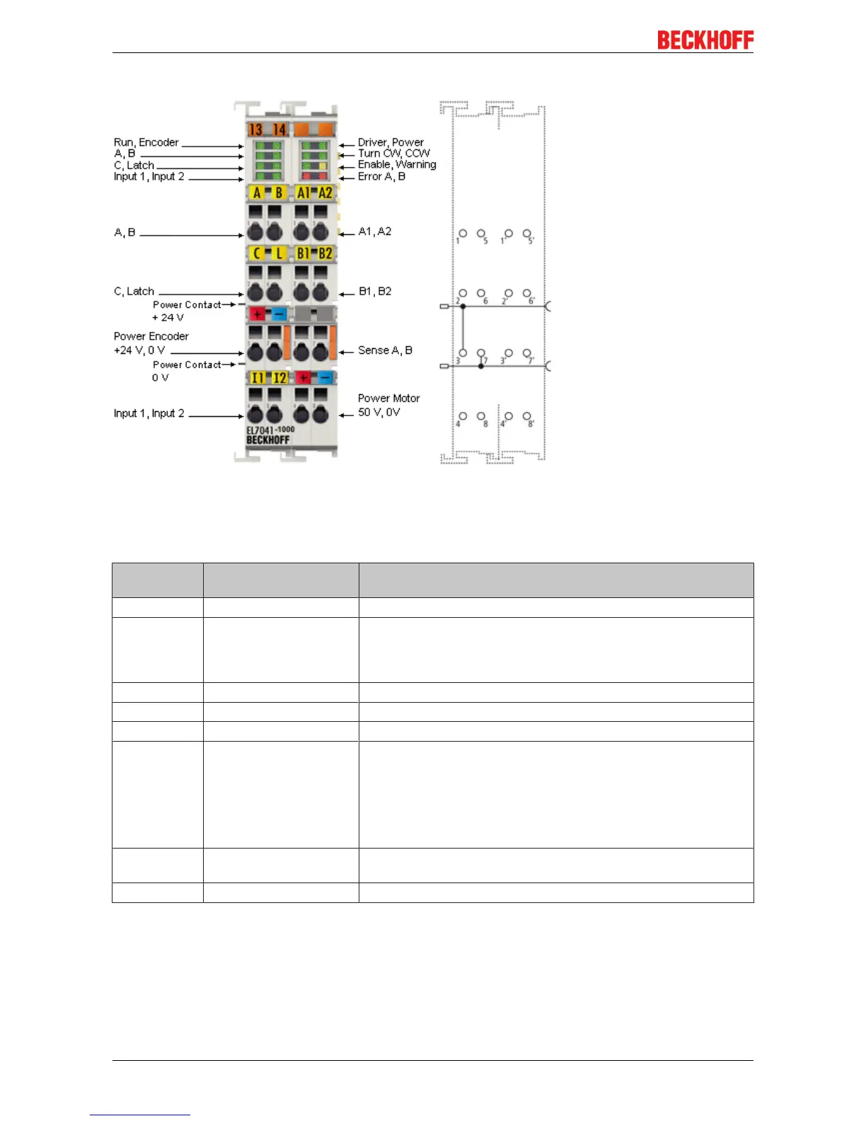
Connection
Fig.42: EL7041-1000 Connection
Connection (left-hand section of the housing)
Terminal
point
Name Signal
1 A Encoder input A
2 C Encoder input C (zero input)
The current counter value is saved as a reference mark in the
latch register if the bit in object 0x7000:01 is set and a rising edge
occurs at encoder input C.
3 Encoder supply +24 V Encoder supply (from positive power contact)
4 Input 1 Digital input 1 (24V
DC
)
5 B Encoder input B
6 Latch/Gate Latch input. The current counter value is saved as a reference
mark in the latch register if
• the bit in object 0x7000:02 is set and a rising edge occurs at
the latch input or
• the bit in object 0x7000:04 is set and a falling edge occurs at
the latch input.
7 Encoder supply
0V
Encoder supply (from negative power contact)
8 Input 2 Digital input 2 (24V
DC
)