TM 55-1520-228-BD
ELECTRICAL AND AVIONICS SYSTEM
11-12. TERMINAL BOARDS.
GENERAL INFORMATION: The terminal
boards provided are all 5 inches in
length.
They are located in the wiring
kit.
They can be cut to shorter
lengths using a hacksaw. The general
procedure is as follows:
LIMITATIONS: Permanent repair.
PERSONNEL/TIME REQUIRED:
1 Soldier
Time will depend on the
wires on the terminal
question.
MATERIALS/TOOLS REQUIRED:
number of
board in
Replacement Terminal Board
(item 10, Appx B)
PROCEDURAL STEPS:
1.
Tag and disconnect wires one at a
time.
2.
Remove terminal board.
3.
Install replacement terminal board.
4.
Connect wires to duplicate the
original installation.
5.
Record BDAR action taken. When
mission is complete, as soon as
practical, repair the equipment/system
using standard maintenance procedures.
11-13. TERMINAL LUGS.
GENERAL INFORMATION: Terminal lugs are
provided in the wiring kit, Table 11-6.
The general procedure for installing
terminal lugs is as follows:
LIMITATIONS: None
PERSONNEL/TIME REQUIRED:
1 Soldier
10 Minutes Per Wire
MATERIALS/TOOLS REQUIRED:
Strippers or Knife
Replacement Terminal Lug (Table
11-6)
Crimp Tool (item 10, Appx B)
PROCEDURAL STEPS:
1.
Select a terminal to fit both the
wire and the terminal stud, Table 11-6.
2.
Strip the wire to the length
specified in Table 11-6.
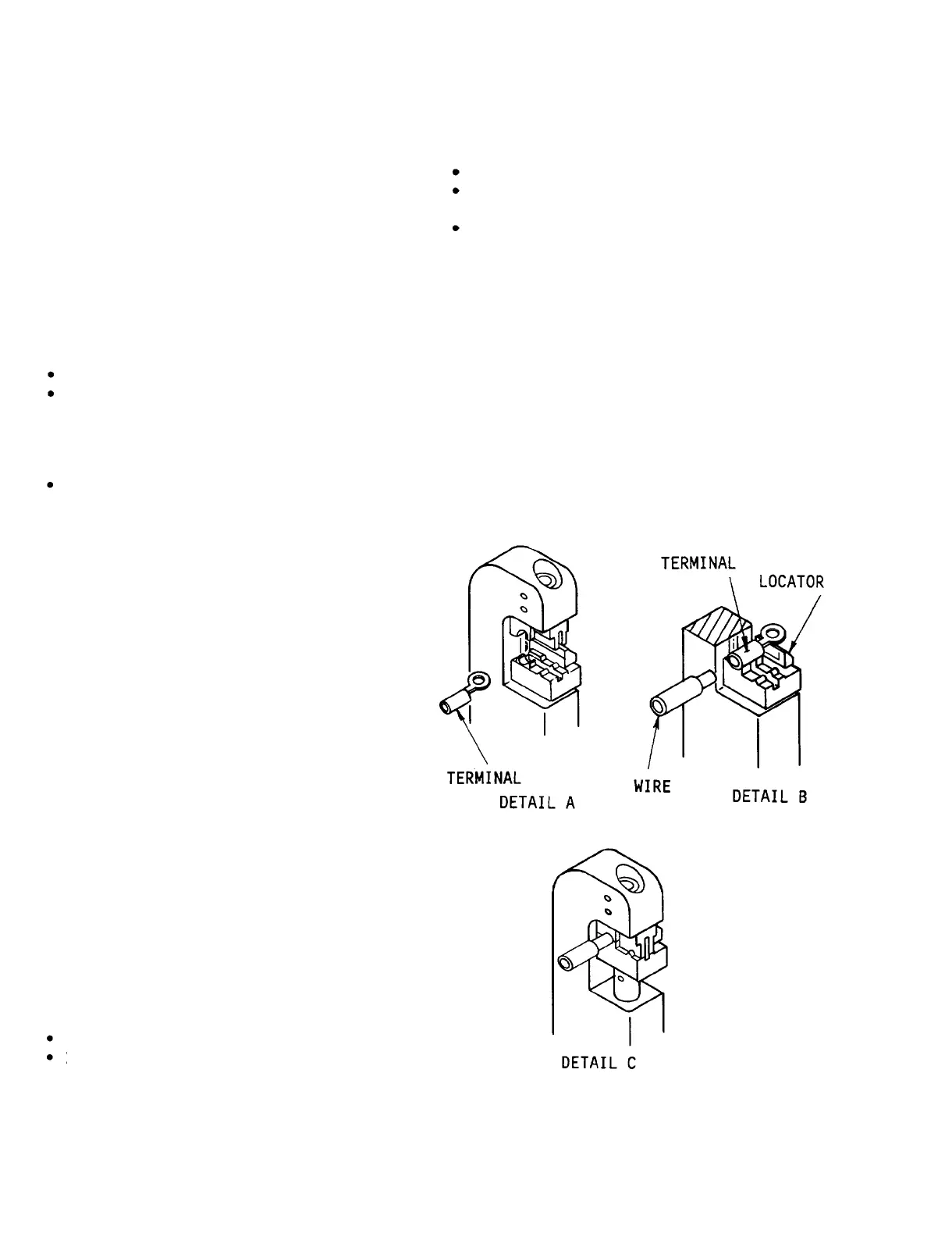
3.
Open the dies of the crimp tool.
Refer to Figure 11-22.
4.
Place terminal in proper cavity of
crimp tool dies (see Detail A of Figure
11-22).
Sizes are stamped below each
cavity on side of die.
Figure 11-22.
Terminal Lug Repair
11-26
 Loading...