Commissioning flow chart (threepart)
21
TGH1361en/11.2009
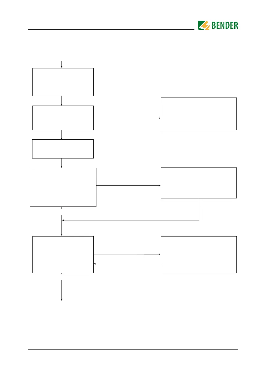
Commissioning of the A-ISOMETER® (2)
Connect the supply
voltage U
S
The A-ISOMETER carries out a
self test. The display indicates
the insulation value after finishing
the measurement.
Shall the basic setting
be changed?
Alarm1 = 40 kW
Alarm2 = 10 kW
K1/K2 = N/O operation
Memory = off
no
yes
Does one of the alarm LEDs
light up?
Select ISO SETUP
(see chapter operation and setting)
no
yes
The insulation value of the system
being monitored is below the preset
response value. Change the response
value or improve the insulation
condition of the system.
Only IRDH275B:
set the clock
Connect the voltage U
n
of the
IT system to be monitored
 Loading...


