Commissioning flow chart (threepart)
22
TGH1361en/11.2009
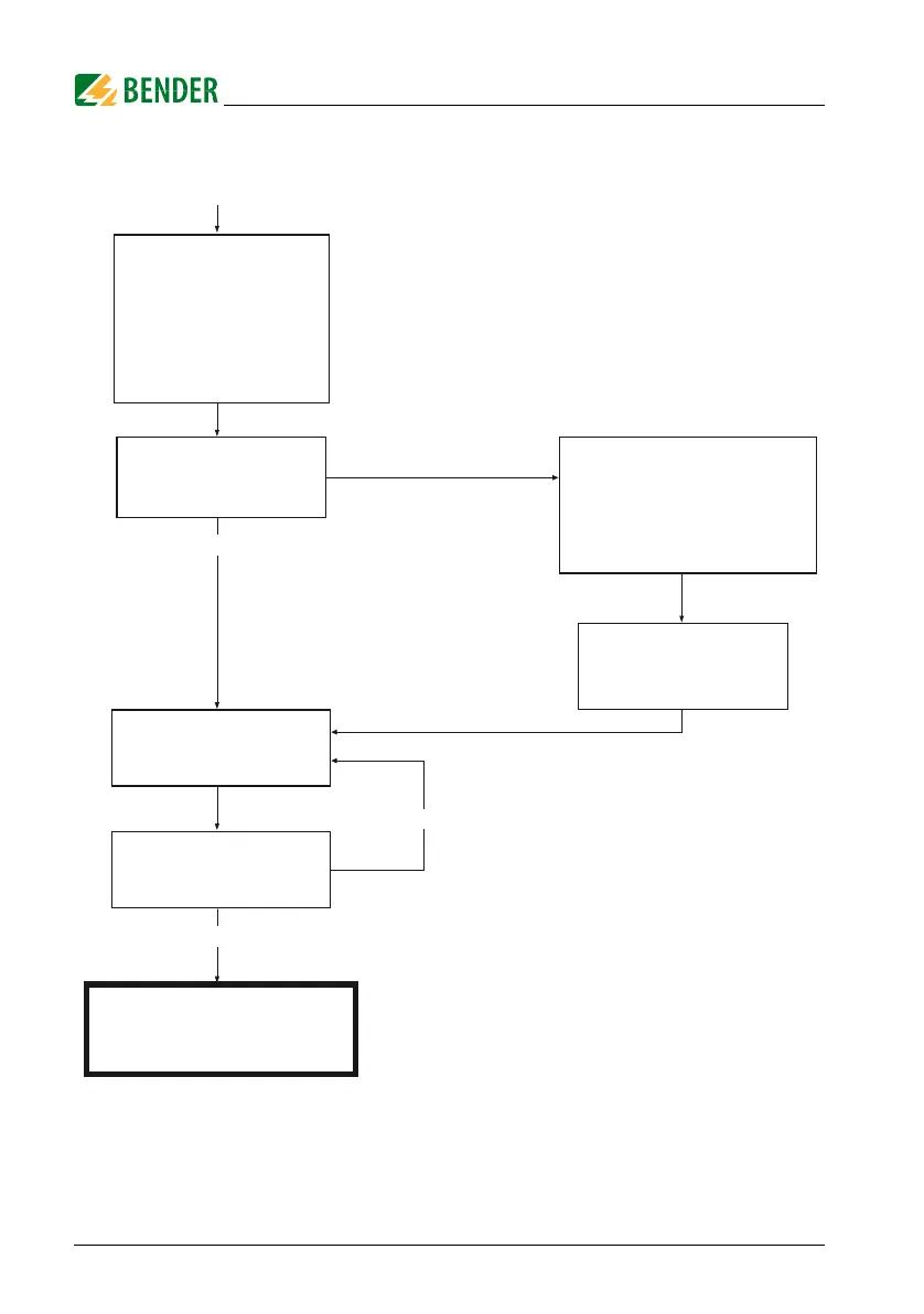
Commissioning of the A-ISOMETER® (3)
In order to check the proper
connection, a functional test
using a suitable resistance is
to be carried out.
Size of the resistance:
50% of the preset response
value Alarm 2.
Check the connecting leads !
Is voltage Un applied to the
terminals L1/L2 ?
When a coupling device is
used, is it correctly connected ?
Check the voltages with a voltmeter !
yes
yes
Remove the resistor !
The IRDH275 is correctly
connected and functions reliably !
Do both alarm LEDs light up?
Did the alarm relays switch ?
yes
no
Do both alarm LEDs light ?
Did the alarm relays switch?
Alarm LEDs extinguished ?
Did the output relays change
their position ?
no
 Loading...


