71
IRDH275BM-7_D00123_06_M_XXEN/07.2018
INDEX
A
Activating and setting the password 47
Alarm LED 1
30
Alarm LED 2
30
Alarm messages
55
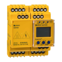
Ankoppelgerät
- Bestellnummern
70
Automatic self test
42
B
Bender Measuring Device Interface 53
BMS bus
- correct arrangement
52
- wrong arrangement
52
BMS-bus
- address ranges
56
BMS-bus address ranges
56
BMS-Master
53
BMS-Slave
54
C
Changing the measuring principle 42
Characteristic curves
65
Characteristics IRDH275BM-7 incl.
AGH675S-7…
18
Commissioning of a BMS network
55
Current output 4-20 mA
66
D
Dimension diagram enclosure
- AGH675S-7MV15
69
- IRDH275
68
Directions for installation
16
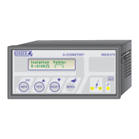
Display in the menu mode
31
Display in the standard mode
31
E
External coupling devices 42
External RESET button
28
External TEST button
28
F
Factory setting 17
Flashing point
54
Function
19
Function input F1/F2
23
H
How to use this manual 7
I
INFO key 30
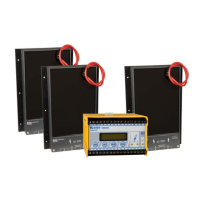
Installation of the coupling device
AGH675S-7…
24