Operation
5.7 Current measurement using the optional BENNINGCC3
5290 / 06/2023 en BENNING PV 1-1+ 33
5.7 Current measurement using the optional
BENNINGCC3
Together with the optional AC/DCcurrent clamp adapter BENNINGCC3, the device can be
used for measuring the operating current of a PVsystem.
Requirements
• BENNINGCC3 (optional accessories)
• Please observe the specifications given in the operating manual of the BENNINGCC3.
• Please observe the requirements for measuring [}page24].
• Approved safety measuring lines
• Corresponding measuring ranges [}page22]
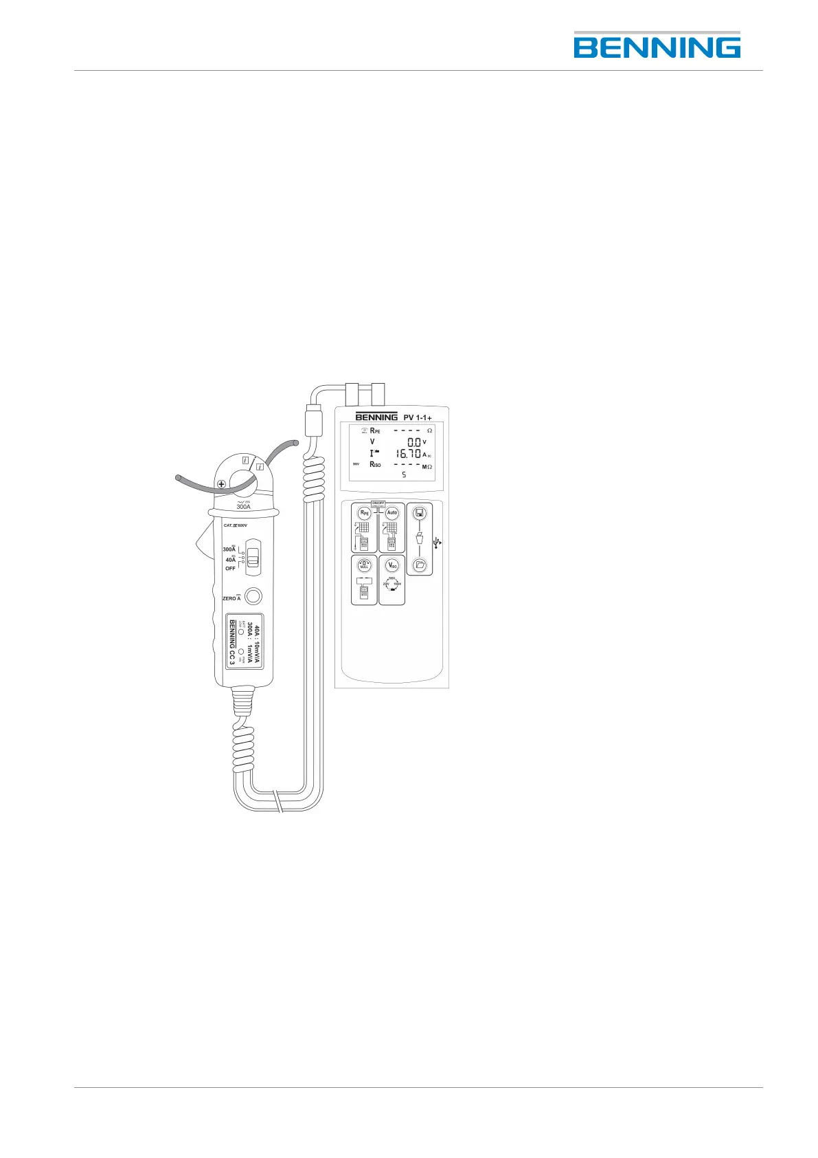
Figure7: Current measurement using the optional BENNING CC 3
Procedure
1. Connect the BENNINGCC3 to the 4mm test sockets of the device.
2. Switch on the BENNINGCC3 and select the 40A range.
3. Switch on the device and press the “V
ISO
“key until the symbol for current clamp
measurement is displayed.
4. For direct current(DC) measurements, press the “Null balance”key of the BENNINGCC3
until a current value of approx. 0A is shown on the digital display of the device.
5. Clamp the single-wire live conductor by means of the current clamp adapter and read the
measured current value on the digital display.
6. Press the “Save”key to store the measured value to the next free storage location available.