5.4 Protective conductor resistance measurement
Operation
5290 / 06/2023 enBENNING PV 1-1+28
5.4 Protective conductor resistance measurement
Requirements
• Please observe the requirements for measuring [}page24].
• Approved safety measuring lines
• Corresponding measuring ranges [}page22]
• In an error-free condition of the PVmodule/ PVstring, no voltage is applied to the
measuring points.
If a voltage higher than 30V is applied to the test probes during measurement, the
measurement will be blocked. If a voltage lower than 30V is applied, a low-impedance
voltage source might trip the built-in fuse of the device [}page41].
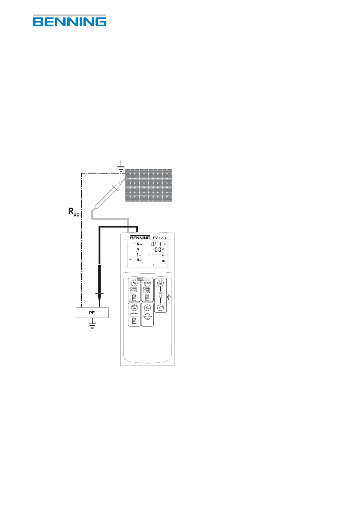
Figure4: Protective conductor resistance
Procedure forsingle measurement
1. Connect the 4mm safety measuring lines to the device [}page25].
2. Only for new safety measuring lines: Please carry out a null balance [}page27].
3. Bring the 4mm safety measuring lines into contact with the measuring points.
4. Press the “R
PE
”key and read the measured value on the digital display.
5. Press the “Save”key to store the measured value to the next free storage location available.