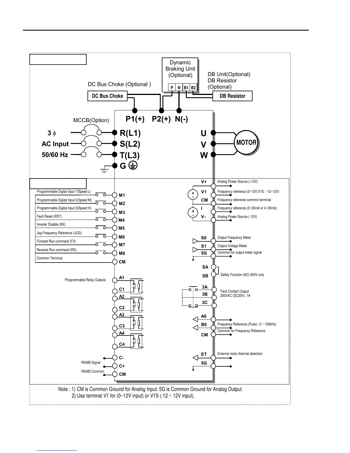
Chapter 3 - Installation
3-4
2) For 50~125HP (37~90KW) and 500~700HP (315~450kW)
AC Input
50/60 Hz
U
V
W
G
R(L1)
S(L2)
T(L3)
N(-)
DB Unit(Optional)
DB Resistor
O
tional
3
MCCB(Option)
M1
M2
M3
M4
M6
M8
M7
MOTOR
Programmable Digital Input 1(Speed L)
Programmable Digital Input 2(Speed M)
Programmable Digital Input 3(Speed H)
Fault Reset (RST)
Jog Frequency Reference (JOG)
Forward Run command (FX)
Reverse Run command (RX)
Common Terminal
P2(+)P1(+)
DC Bus Choke (Optional )
Dynamic
Braking Unit
(Optional)
P N B1
B2
DC Bus Choke DB Resistor
M5
Inverter Disable (BX)
V+
V1
CM
V-
I
Analog Power Source (+12V)
+
-
+
-
Analog Power Source (-12V)
Frequency reference (0~20mA or 4~20mA)
Frequency reference (0~12V,V1S : -12~12V)
Frequency reference common terminal
S1
S0
5G
Output Frequency Meter
Output Voltage Meter
Common for output meter signal
CM
B0
A0
Common for Frequency Reference
Frequency Reference (Pulse : 0 ~ 100kHz)
5G
ET
External motor thermal detection
A1
C1
A2
C2
A3
C3
A4
C4
C-
C+
CM
RS485 Signal
RS485 Common
CM
Note : 1) CM is Common Ground for Analog Input. 5G is Common Ground for Analog Output.
2) Use terminal V1 for (0~12V input) or V1S (-12 ~ 12V input).
Programmable Relay Outputs
Fault Contact Output
250VAC (DC30V), 1A
3A
3C
3B
SA
SB
Safet
Function
NC
600V onl
Main Power Circuit
Control Circuit
250 VAC, 1A

 Loading...