Chapter 3 - Installation
3-13
3.2.4 TerminalLayout
Screw Terminals
7.5 ~ 40 HP (230V/460V/575V)
R(L1) S(L2) T(L3) G P1(+) P2(+) N(-) U V W
Bus Bar Terminals
50 ~ 125 HP (460V/575V) / 500 ~ 700 HP (460V)
R(L1) S(L2) T(L3) P1(+) P2(+) N(-) U V W
Bus Bar Terminals
150 ~ 400 HP (460V/575V)
R(L1) S(L2) T(L3) P2(+) N(-) U V W
Note) P1 terminal is not provided for wiring.
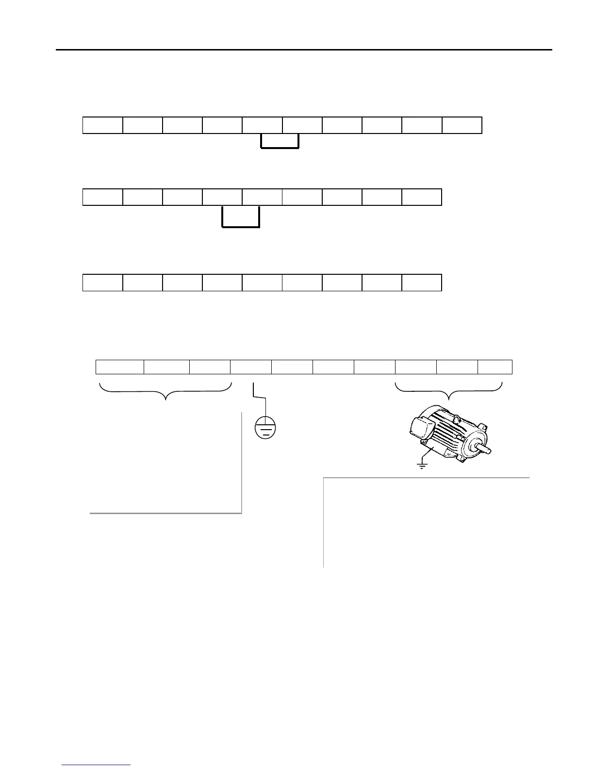
Power and Motor Connection Example (7.5~40 HP drives)
R(L1) S(L2) T(L3) G P1(+) P2(+) N(-) U V W
Jumper
Jumper
Power supply must be
connected to the R, S, and T
terminals. Connecting it to the
U, V, and W terminals causes
internal damages to the inverter.
Arranging the phase sequence is
not necessary.
Motor should be connected to the U, V,
and W terminals.
If the forward command (FX) is on, the
motor should rotate counter clockwise when
viewed from the load or shaft side of the
motor. If the motor rotates in the reverse,
switch the U and V terminals.
Ground
r
n

 Loading...