Chapter 3 - Installation
3-16
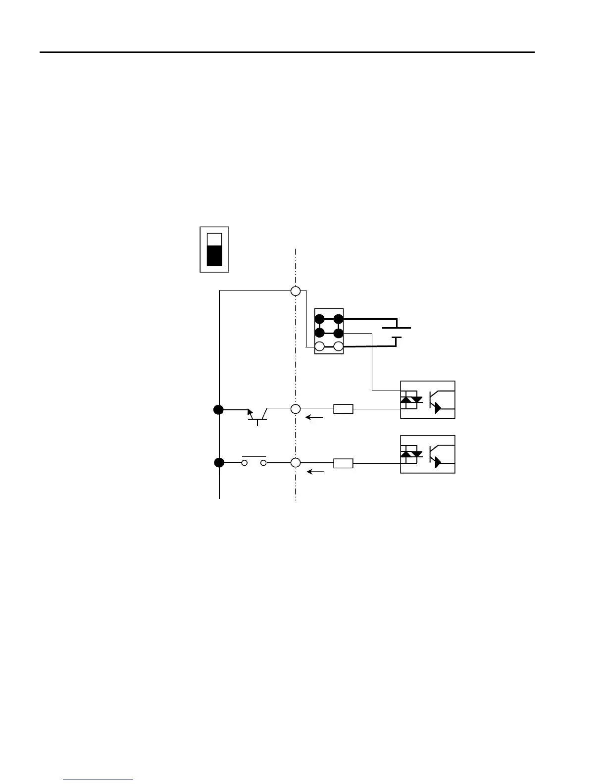
(3) Control circuit operation
RSI-SG provides NPN/PNP modes for activating the input terminals on the control board. Each connection
method is described below.
Method 1: NPN mode, Mx – CM
NPN mode: when J1 switch is set to NPN mode (downward), use Mx to CM for connection of an external
contact (switch, relay or transistor). With contact closed, the control board input terminal is activated
(turned ON) using the internal 24V power supply.
Internal P/S (24V)
CM(24G)
J1 PNP
(Factory default: NPN)
NPN
M7(FX)
M8(RX)
(For NPN TR connection)
(For RELAY connection)

 Loading...