04/03 347 LB 444
35
5.3 Electrical Connections
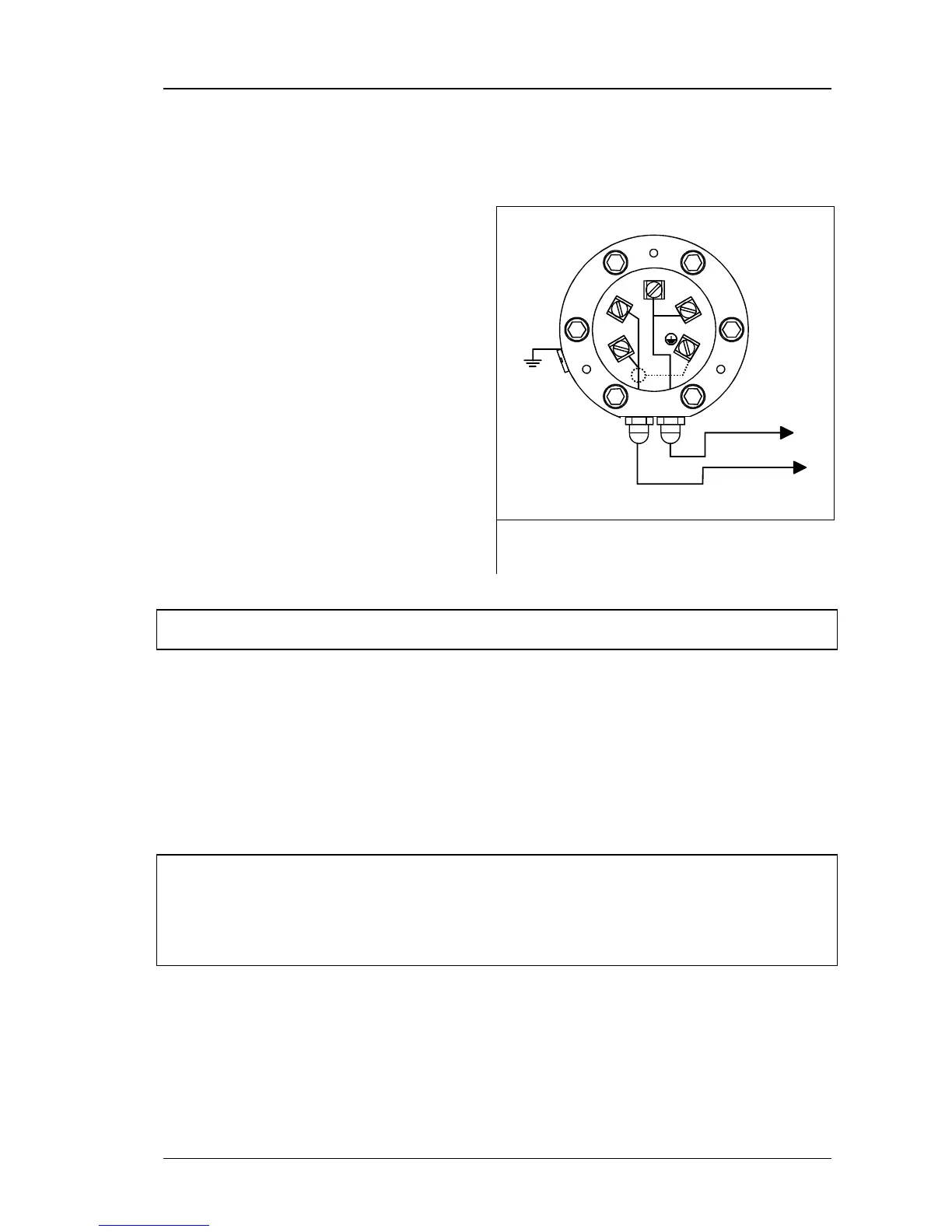
5.3.1 Detector
4
3
2
1
5
LB 440
PA
Pt 100
Switch off the evaluation unit before
connecting the scintillation counter.
Open the screws and remove the con-
nection box cover to expose the connec-
tion area.
With fail-safe installations, connect the
detector to the potential equalization bar
of the installation.
The detector is connected to the evalua-
tion unit via a 2-wire cable with approx.
8…10 mm diameter and a cross-section
of 1 mm
2
. A screen cable may be used
in installations with extremely strong
electrical interferences. The screen may
be placed only on one side of the detec-
tor.
Figure 20:
Cable connections at detector
In fail-safe installations the permissible inductivities and capacities of the con-
nection cable have to be observed in accordance with the Ex test certificate.
Please observe the maximum cable lengths between evaluation unit and detector (see
chapter 9 TECHNICAL DATA.
When installing the connection cable, make sure that water cannot get into the connec-
tion box via the cable. With ambient temperatures >70°C, the installed cable has to be
protected to prevent exceeding of the temperature limits of the cable. Following connec-
tion, check that the connection box is carefully closed and the cable bushing properly
sealed.
If a resistance thermometer is connected, the cables coming from the Pt 100 are passed
through the second cable bushing to terminals 3 and 4.
For equipment installed in the Ex-area, please observe the special requirements
for the cable and the preparation of the connection wires.
The detector LB 44... has to be used for installation in the Ex-area. The detector
LB 54.. may only be used for non Ex-applications.
The evaluation unit must always be installed outside the Ex-area.
A special transmission technique ensures interference suppression. Nevertheless, the ca-
ble should not be installed together with power cables.