04/03 347 LB 444
40
Shielding Container for Installation in a Container
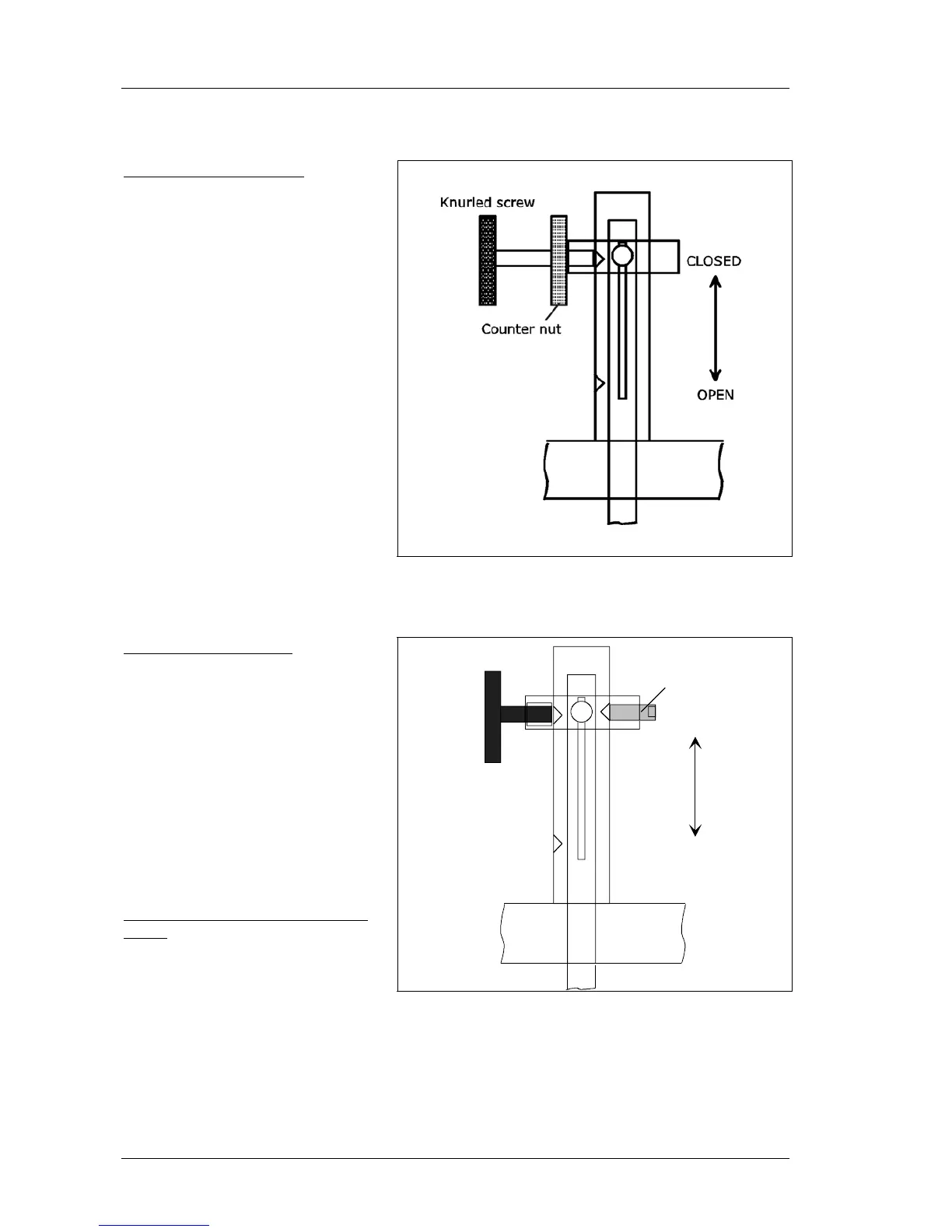
Version with knurled nut
• Open padlock and turn pro-
tective cap until it can be ta-
ken off.
• Open knurled nut and pull
source forward to “OPEN” po-
sition.
• Turn counter nut completely
back toward screw head.
Firmly tighten knurled nut.
• Firmly turn counter nut to-
ward the front, in the direc-
tion of the protection pipe
and tighten it firmly.
• Attach protection cap again
and secure it with a padlock.
Figure 23:
Locking mechanism with knurled nut
Version with spring pin
• Open padlock and turn pro-
tective cap until it can be ta-
ken off. Open fastening
screw.
• Pull out spring pin and push
source locking lever toward
the front in “OPEN” position
until the spring pin engages.
• Firmly tighten locking screw
again.
• Attach protection cap again
and secure it with a padlock.
Shielding with pneumatic locking
drive:
• Open pressure supply.
CLOSED
OPEN
Spring pin
Locking screw
Figure 24: Locking mechanism with spring pin
Turn instrument power supply on . Manufacturer’s name, version number and device
type are displayed.