04/03 347 LB 444
38
6. GETTING STARTED
6.1 Quick Installation Overview
Page
Install detector and source with shielding on a container or pipeline. 28
Use water cooling if temperatures exceed 50°C. 32
To perform temperature compensation with Pt 100 (option), install resis-
tance thermometer on pipeline such that the measured temperature = product
temperature.
34
Connect detector to LB 444 via two-wire cable. Connect cable to terminal 2a
and 2c of evaluation unit.
35
Install evaluation unit. 36
For temperature compensation via external current input (option): Con-
nect temperature sensor to terminal 28a+ and 28c- (not possible for mass flow
measurement).
49
Mass flow measurement: The volume current signal can be supplied via ter-
minals 28a / 28c. Temperature compensation is possible only via Pt 100 con-
nected to the detector.
26
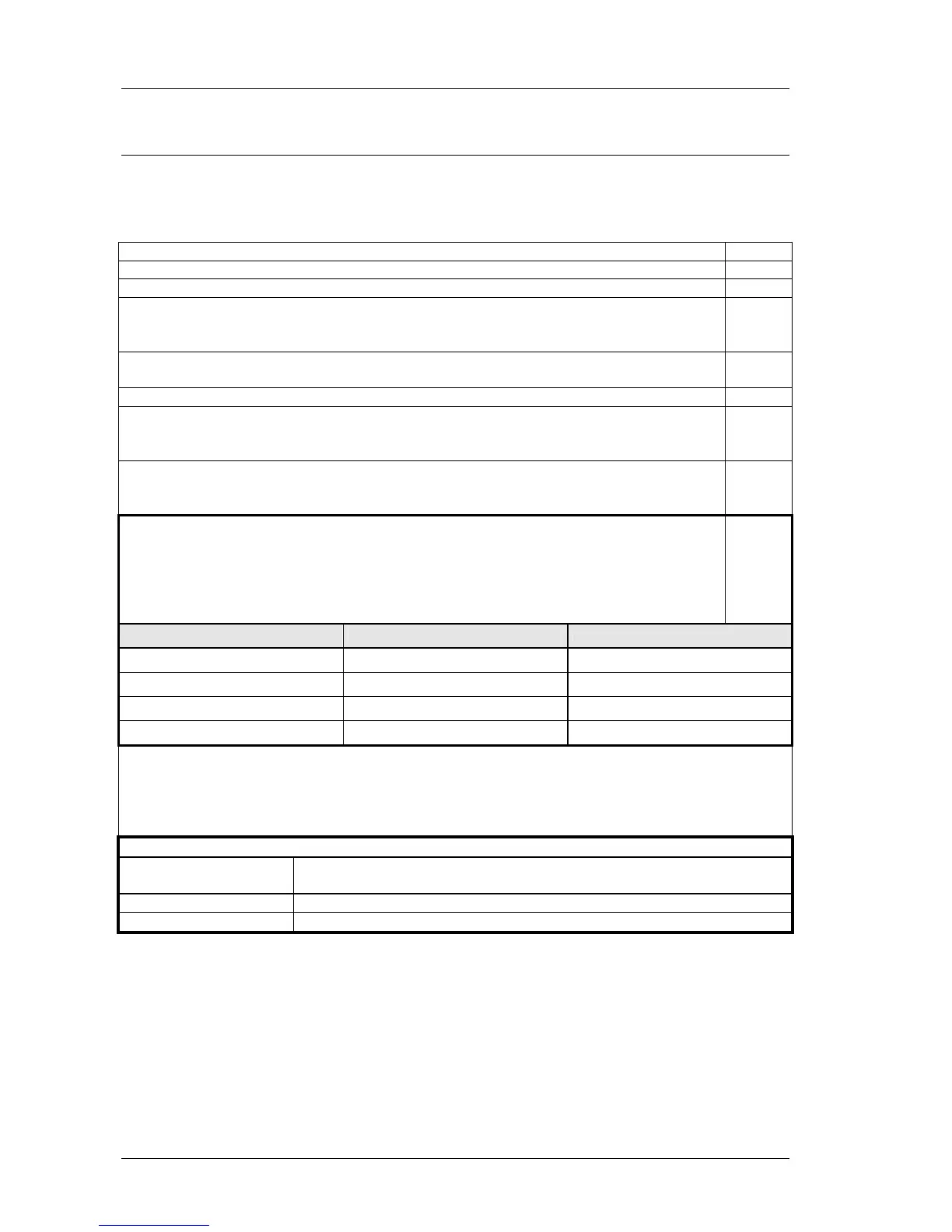
External product selection:
If you want to install external product selection, both digital inputs have to be
used so that 4 different products can be selected.
Digital input 1 (DI 1): 18a / 18c
Digital input 2 (DI 2): 20a / 20c
21
Product DI 1 DI 2
1 0 0
2 0 1
3 1 0
4 1 1
Digital input 3 (DI 3): 22a /22c. External start/stop signal
Digital input 3 can be used for the following signals:
a) Start/Stop in batch mode
b) Stop continuous measurement (“freezing” measurement; “HALT” appears on display)
Digital outputs (relays): These outputs can be used for the following signals:
12a, 12c: Rel. 2: Min. 1, max. 1, detector temperature, mass pulse (only for mass
flow)
14a, 14c: Rel. 3: Min. 1, max. 1, detector temperature
16a, 16c: Rel. 1: Error message