04/03 347 LB 444
82
10.5 Detector
10.5.1 Checking the Crystal-Multiplier Assembly
A plateau that is too small or too steep indicates faults in the crystal-multiplier assembly.
Please proceed as follows to perform a visual inspection of crystal and multiplier:
Switch off the scintillation counter before opening the instrument.
Do not perform the check in bright daylight, as this may damage the photo
cathode of the photo multiplier.
Open the scintillation counter by removing the cover of the
connection box first and then the screws of the base. The
entire electronics (1) with the crystal/multiplier combina-
tion can then be detached from the housing.
Remove photo multiplier combination from base (2) and
unscrew ring nut (3) on front panel. The multiplier (4) in-
cluding crystal (5) can now be detached from the Mu-metal
shielding (6).
A thin layer of silicone oil between crystal and multiplier
ensures optical coupling; silicone oil is rather viscous, par-
ticularly at low temperatures. Carefully detach the crystal
from the multiplier window by gently sliding the crystal
sideways. Do not wipe off the silicone oil!
Check:
The crystal must be perfectly clear inside and not show
any dull areas. Its typical color is white. A yellowish to
brownish coloring is a sign of thermal overload and indi-
cates that the crystal has to be replaced. The surrounding
white reflecting layer must not be damaged. You can only
check the photo multiplier for glass breakage or other me-
chanical damage. Other faults cannot be identified by visual
checks alone. However, if the crystal does not show any
faults, a bad plateau indicates that the photo multiplier is
faulty.
(a)
(b)
(c)
3
5
4
6
2
1
The multiplier window is coated with a vapor-deposited
layer acting as photocathode. This layer gives the window a
brownish tint similar to smoked glass. If this layer is no
longer present or if it is stained, then the photocathode has
been destroyed (e.g. by overheating, glass breakage, or
incident light), and the multiplier must be replaced. Faults
caused by damage to the dynode systems (e.g. by exces-
sive vibration) cannot be identified by appearance. If in
doubt, replace the multiplier.
The glass pane at the mating face to the photo multiplier
must not show any cracks.
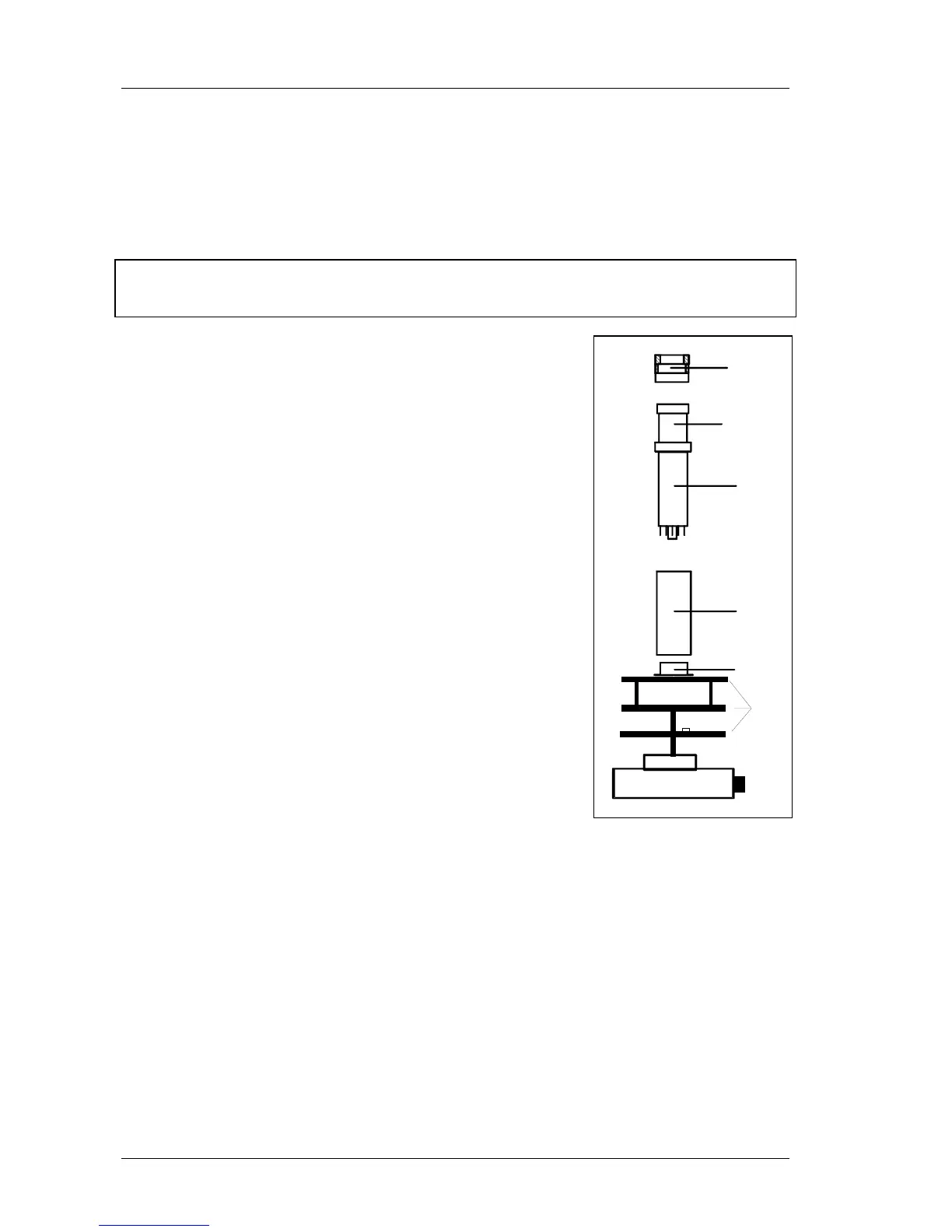
Figure 32: Assembly of
scintillation counter
1 = Electronics part with
(a) CPU, b) HV, (c)
voltage divider
2 = Base
3 = Ring nut
4 = Photomultiplier
5 = Crystal
6 = Mu-metal shielding
Before re-assembly, apply a drop of clean silicon oil between crystal and multiplier and
distribute it evenly by gentle rubbing to ensure sound optical connection between both