04/03 347 LB 444
36
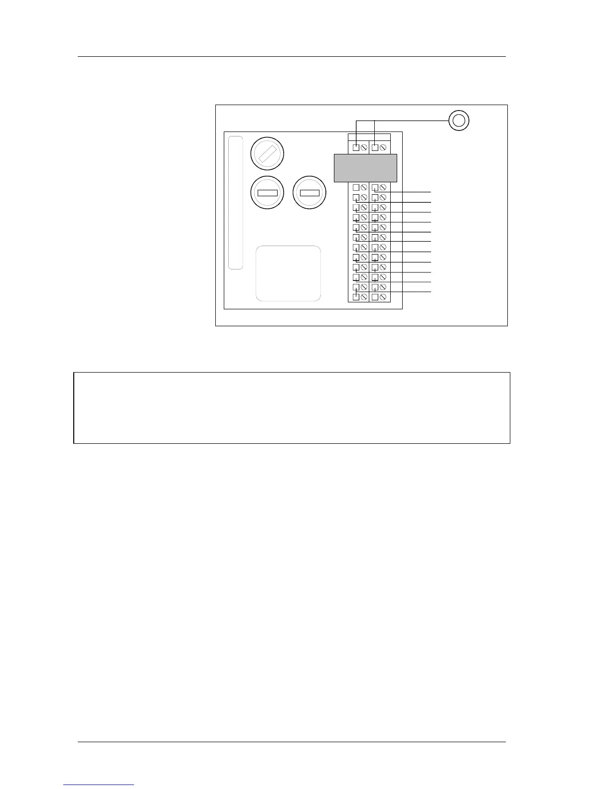
5.3.2 Evaluation Unit LB 444
c a
2
4
6
8
10
12
14
16
18
20
22
24
26
28
30
32
Relay 2
Relay 3
Relay 1
Power
supply
2(-) 1 (+)
Detector
RS 485
0/4 - 20 mA Off
LB 444
Voltage
selector
Fuses
Dig. IN 1
Dig. IN 2
Dig. IN 3
Spacer
24 V DC
0/4 - 20 mA On
Connect cable on the
rear panel of the
evaluation unit as
shown in the wiring dia-
gram in the appendix to
this manual.
Figure 21:
Terminal connection evaluation unit (rear panel)
Connect the instrument only to the appropriate line voltage.
All safety previsions regarding the power distributor have to be observed.
A separate fuse protection and an easy to access shutoff have to be foreseen,
since the evaluation unit does not include its own mains switch.
The spacer ensures the proper distance between the fail-safe output circuit
(2a/2c) and the not fail-safe terminals. Do not remove it.
Refer to the wiring diagram in the appendix to this manual information regarding the
connections.
Detector (2a/2c)
The detector connection circuit of the evaluation unit is designed as a fail-safe device.
The detector includes a connection box according to protection type “increased safety”
“e” and a pressure-proof sealed housing according to protection type “Ex d”.
For fail-safe installation, the cable ends on the strip terminal have to be protected by a
10 mm long plastic shrinkage tube (see also the connection diagram).
Auxiliary energy (24 V DC, not insulated, max. 100 mA) can be used e.g. for operation of
an external mass counter.
Relay 2 (12a/12c)
The relay can be used for the following functions:
Min. alarm, max. alarm, detector temperature, mass pulse.
Relay 3 (4a/14c)
Functions:
Min. alarm, max. alarm, detector temperature
Relay 1 (16a/16c)
The relay can be used to signal errors. Contact opens if error occurs.