ENGINE
EAS20472
ENGINE
EAS20520
ADJUSTING THE VALVE CLEARANCE
The following procedure applies to all of the
valves.
IP
• Valve clearance adjustment should be made
on a cold engine, at room temperature.
• When the valve clearance is to be measured or
adjusted, the piston must be at top dead center
(TDC) on the compression stroke.
1. Remove fuel tank
2. Disconnect:
• Spark plug cap
3. Remove:
4. Spark plug
5. Cylinder head c
over
6. Cylinder head cover gasket
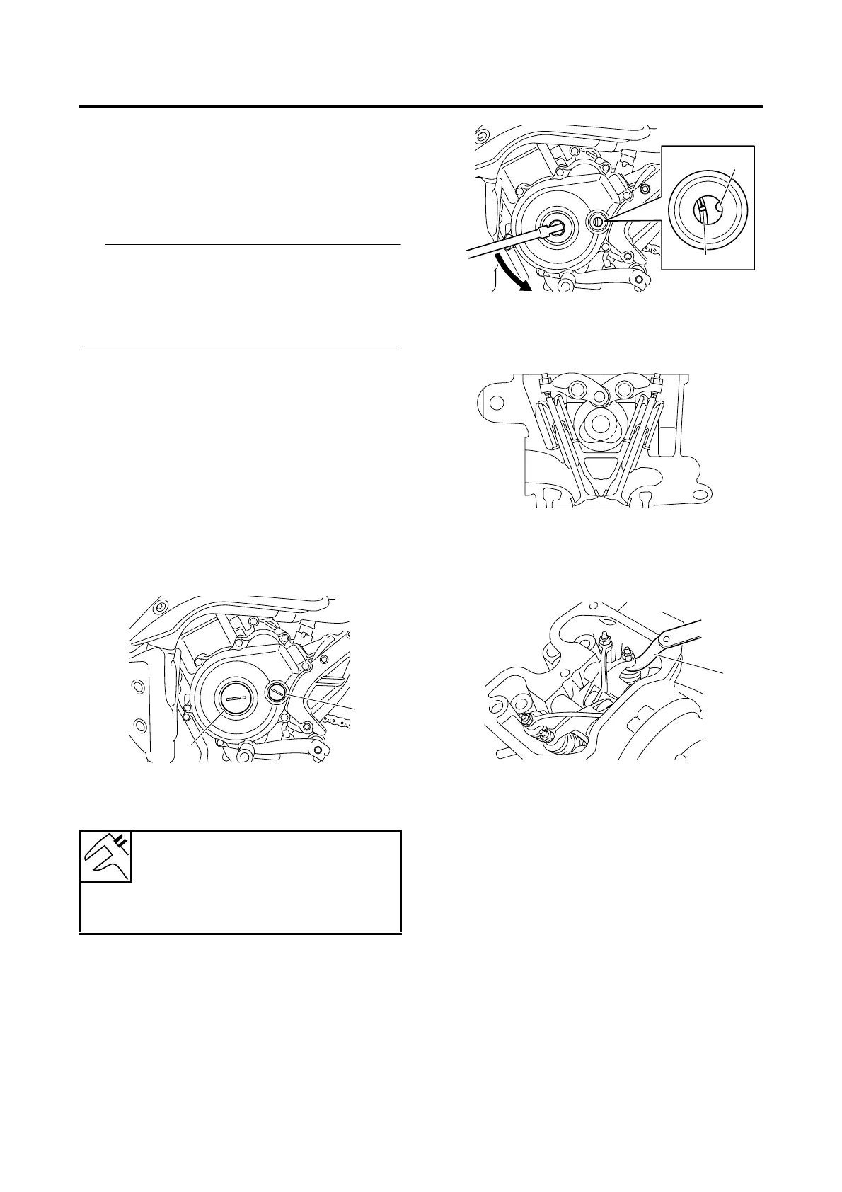
4. Remove:
• Timing mark accessing screw “1”
• Crankshaft end accessing screw “2”
5. Measure:
• Valve clearance
Out of specification → Adjust.
▼▼▼▼▼▼▼▼▼ ▼ ▼▼▼▼▼▼▼▼▼ ▼ ▼▼▼▼ ▼ ▼▼▼▼ ▼▼▼
a. Turn the crankshaft counterclockwise.
b. Align the TDC mark “a” on the generator rotor
with the stationary pointer “b” on the genera-
tor cover.
c. Check that the cam lobes are positioned as
shown in the illustration.
d.
Measure the valve clearance with a thickness
gauge “1”.
Out of specification → Adjust.
▲▲▲▲▲▲▲▲▲ ▲ ▲▲▲▲ ▲ ▲▲▲▲ ▲ ▲▲▲▲ ▲ ▲▲▲▲ ▲▲▲
6. Adjust:
• Valve clearance
▼▼▼▼▼▼▼▼▼ ▼ ▼▼▼▼ ▼ ▼▼▼▼ ▼ ▼▼▼▼ ▼ ▼▼▼▼ ▼▼▼
a. Loosen the locknut “1”.
b. Insert a thickness gauge “2” between the end
of the adjusting screw and the valve tip.
Valve clearance (cold)
Intake
0.10–0.14 mm (0.0039–0.0055 in)
Exhaust
0.20–0.24 mm (0.0079–0.0094 in)
2
1
b
a
1
 Loading...