ELECTRICAL COMPONENTS
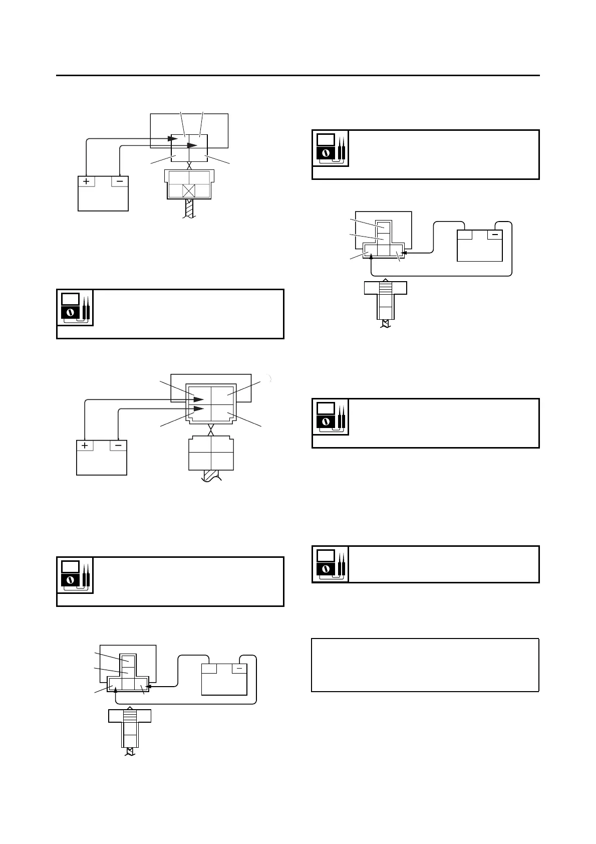
Starter relay
Starting circuit cut-off relay
Headlight relay
Radiator fan motor relay
EAS22B1024
CHECKING THE TURN SIGNAL RELAY
1. Check:
• Turn signal relay input voltage
Out of specification → The wiring circuit from
the main switch to the turn signal relay cou-
pler is faulty and must be repaired.
▼▼▼▼▼▼▼▼▼ ▼ ▼▼▼▼ ▼ ▼▼▼▼ ▼ ▼▼▼▼ ▼ ▼▼▼▼ ▼▼▼
a. Connect the pocket tester (DC 20 V) to the
turn signal relay terminal as shown.
1. Positive battery terminal
2. Negative battery terminal
3. Positive tester probe
4. Negative tester probe
Result
Continuity
(between “3” and “4”)
1. Positive battery terminal
2. Negative battery terminal
3. Positive tester probe
4. Negative tester probe
Result
Continuity
(between “3” and “4”)
1. Positive battery terminal
RR/W
R/B L/B
21
43
1
3
2
4
R/B
L/B
R/W
L/W
+
R/Y
L/
B
R/Y
W/
B
1
2
3
4
2. Negative battery terminal
3. Positive tester probe
4. Negative tester probe
Result
Continuity
(between “3” and “4”)
1. Positive battery terminal
2. Negative battery terminal
3. Positive tester probe
4. Negative tester probe
Result
Continuity
(between “3” and “4”)
Turn signal relay input voltage
DC 12 V
• P
ositive tester probe →
brown “1”
• Negative tester probe →
ground
+
R/W
L
R/B
G/B
1
2
3
4