ELECTRICAL COMPONENTS
EAS28940
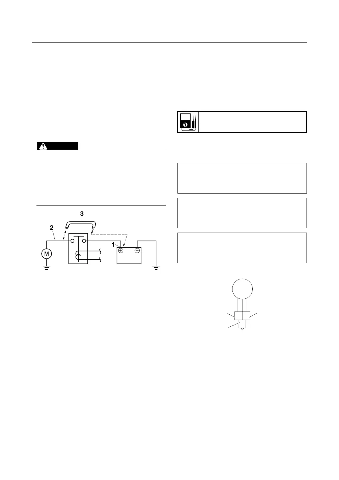
CHECKING THE STARTER MOTOR
OPERATION
1. Check:
2. Starter motor operation
Does not operate → Perform
the electric
starting system troubleshooting, starting with
step 4.
▼▼▼▼▼▼▼▼▼ ▼ ▼▼▼▼▼▼▼▼▼ ▼ ▼▼▼▼ ▼ ▼▼▼▼ ▼▼▼
a. Connect the positive battery terminal “1” and
starter motor lead “2” with a jumper lead “3”.
WARNING
EWA13810
• A wire that is used as a jumper lead must
have at least the same capacity of the bat-
tery lead, otherwise the jumper lead may
burn.
• This check is likely to produce sparks,
therefore, make sure no flammable gas or
fluid is in the vicinity.
b. Check the starter motor operation.
▲▲▲▲▲▲▲▲▲ ▲ ▲▲▲▲▲▲▲▲▲ ▲ ▲▲▲▲ ▲ ▲▲▲▲ ▲▲▲
EAS28150
CHECKING THE STATOR COIL
1. Disconnect:
• Stator coil coupler
(from the wire harness)
2. Check:
• Stator coil resistance
Out of specification → Replace the crank-
shaft position sensor/stator assembly.
▼▼▼▼▼▼▼▼▼ ▼ ▼▼▼▼ ▼ ▼▼▼▼ ▼ ▼▼▼▼ ▼ ▼▼▼▼ ▼▼▼
a. Connect the pocket tester (Ω × 1) to the stator
coil coupler as shown.
b. Measure the stator coil resistance.
▲▲▲▲▲▲▲▲▲ ▲ ▲▲▲▲ ▲ ▲▲▲▲ ▲ ▲▲▲▲ ▲ ▲▲▲▲ ▲▲▲
EAS28170
CHECKING THE RECTIFIER/REGULATOR
1. Check:
• Charging voltage
Out of specification → Replace the rectifi-
er/regulator.
Stator coil resistance
0.448–0.672 Ω at 20 °C (68 °F)
• Positive tester probe →
wh
ite “1”
• Negative tester probe →
white “2”
• Positive tester probe →
white “1”
• Negative tester probe →
white “3”
• Positive tester probe →
white “2”
• Negative tester probe →
white “3”
1
2
3
WW
W