ELECTRICAL COMPONENTS
b. Set the main switch to “ON”.
c. Measure the turn signal relay input voltage.
▲▲▲▲▲▲▲▲▲ ▲ ▲▲▲▲▲▲▲▲▲ ▲ ▲▲▲▲ ▲ ▲▲▲▲ ▲▲▲
2. Check:
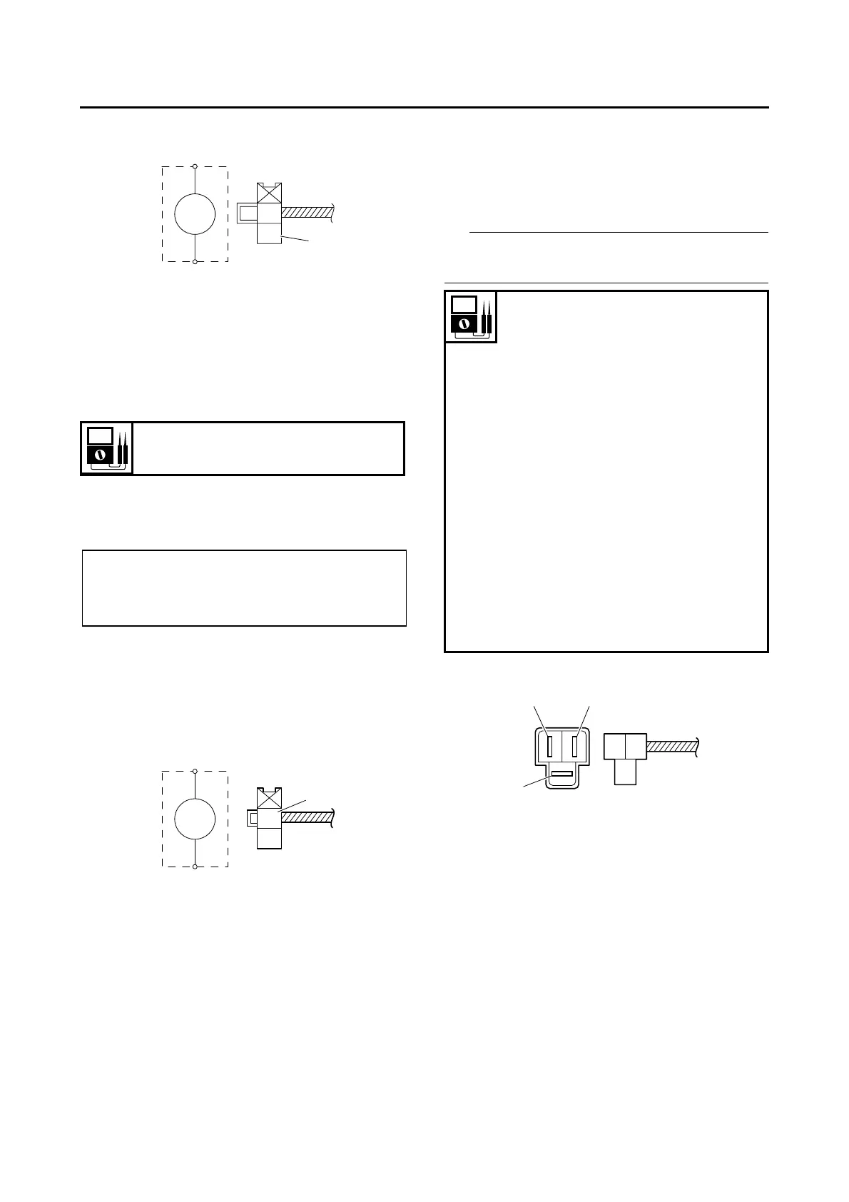
• Turn signal relay output voltage
Out of specification → Replace.
▼▼▼▼▼▼▼▼▼ ▼ ▼▼▼▼▼▼▼▼▼ ▼ ▼▼▼▼ ▼ ▼▼▼▼ ▼▼▼
a. Connect the pocket tester (DC 20 V) to the
turn signal relay terminal as shown.
b. Set the main switch to “ON”.
c. Measure the turn signal relay output voltage.
▲▲▲▲▲▲▲▲▲ ▲ ▲▲▲▲▲▲▲▲▲ ▲ ▲▲▲▲ ▲ ▲▲▲▲ ▲▲▲
EAS28050
CHECKING THE DIODE
1. Check:
• Diode
Out of specification → Replace.
IP
The pocket tester or the analog pocket tester
readings are shown in the following table.
▼▼▼▼▼▼▼▼▼ ▼ ▼▼▼▼ ▼ ▼▼▼▼ ▼ ▼▼▼▼ ▼ ▼▼▼▼ ▼▼▼
a. Disconnect the diode from the wire harness.
b. Connect the pocket tester (Ω × 1) to the diode
terminals as shown.
c. Check the diode for continuity.
d. Check the diode for no continuity.
▲▲▲▲▲▲▲▲▲ ▲ ▲▲▲▲ ▲ ▲▲▲▲ ▲ ▲▲▲▲ ▲ ▲▲▲▲ ▲▲▲
EAS28060
CHECKING THE SPARK PLUG CAP
1. Check:
• Spark plug cap resistance
Out of specification → Replace.
Turn signal relay output voltage
DC 12 V
• P
ositive tester probe →
brown/white “1”
• Negative tester probe →
ground
Br/W
Br
1
Br/W
Br
1
No continuity
Positive tester probe →
blue/black “1”
Negative tester probe → sky
blue/white “2”
Continuity
Positive tester probe → sky
blue/white “2”
Negative tester probe →
blue/black “1”
No continuity
Positive tester probe →
red/black “3”
Negative tester probe → sky
blue/white “2”
Continuity
Positive tester probe → sky
blue/white “2”
Negative tester probe →
red/black “3”
L/B
R/B
Sb/W
13
2