30
100%
100%
0%
0%
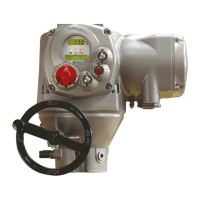
BIFFI F01-2000 ELECTRIC ACTUATOR
INSTRUCTION AND OPERATING MANUAL
Default #2
Monitor relay
- main voltage failure
- lost phase
- local/off selected
- local stop pressed
- manual operation
- internal temperature alarm
- K1 contactor failure
- K2 contactor failure
- position sensor failure
- speed sensor failure
- configuration error
- HW error
- motor over-temperature
- over-torque
- jammed valve
- low lithium battery (if present)
- mid-travel alarm
Auxiliary relays
AS1: open limit; break
AS2: close limit; break
AS3: position >90%; break
AS4: position <5%; break
AS5: motor running; make
AS6: remote selected; make
AS7: warning; make
AS8: local selected
Configure output relays
• Press YES to change the monitor
relay or NO to change auxiliary relays
AS1, 2, 3, 4, 5, 6, 7, 8.
Monitor relay
• Press YES or NO to enable or disable the
following situations from the conditions
which de-energize the monitor relay: motor
over-temperature, over-torque, jammed
valve, manual override, ESD signal on,
low lithium battery (if present), local STOP
pressed, LOCAL/OFF selected.
Auxiliary relays AS1, 2, 3, 4, 5, 6, 7 and 8
• Press NO to answer prompt
“MONITOR RELAY change?”.
• Press YES to change AS1, press NO to select
the other relays.
• Press YES if the condition associated to AS1
relay is correct, press NO to scrolls the list of
conditions and press YES to set.
• Press YES or NO to either confirm or change
the type of contact when the condition
occurs (break, make). Since relay AS8 is
change-over, this option is not available.
• Press NO to pass to AS2 and then repeat the
procedure for the other relays.
• Press NO to exit.
9�1�7 Positioner
The positioning function is only available in
inching or modulating F01-2000 actuators
and allows to position the valve according to a
“position request R%” command signal.
The positioning function compares the present
actuator position % with the position request
R%, and if the difference is greater than the
dead band the actuator is driven to reach the
new requested position.
The “position request R%” signal may either be
received from the bus or the 4-20 mA analog
input. If the F01-2000 is set to receive the
position request R% from the bus, a fieldbus
interface card must be present, or a Hardware
alarm will be generated. If the F01-2000 is
set to receive the position request R% from
the 4-20 mA generator, the Ain/Aout card
must be present, or a Hardware alarm will be
generated.
The following options can be configured via
local operator interface:
- Dead band: configurable from “position
resolution%” to 25.5% of the maximum
position error. The configured value should be
great enough to avoid the hunting effect.
- Polarity of the 4-20 mA position request
signal: it allows to reverse the relationship
between the 4-20 mA input signal and
the “position request R%”, according to
the following diagrams. The option is not
available when the F01-2000 is set to receive
the “position request R%” from the bus.
- Motion inhibit time: it allows to adjust the
length of the delay time between two cycles
of the motor. It can be configured from
1 to 255 secs and allows to set the maximum
number of start/hour of the electrical motor.
- % MIN and % MAX, 4-20 mA input signal
range: it allows to change the relationship
between the input signal and the position
request R%. This function is useful when
a single 4-20 mA signal is used to control
the position of 2 valves (e.g.: split range
applications). The option is not available when
the F01-2000 is set to receive the “position
request R%” from the bus.
INPUT 4-20 mA
POLARITY: 4 mA = CL
Input request
20 mA
4 mA
Position %
20 mA
4 mA
INPUT 4-20 mA
POLARITY: 4 mA = OP
Input request
Position %
Default #1
Monitor relay
- main voltage failure
- lost phase
- local/off selected
- local stop pressed
- manual operation
- internal temperature alarm
- K1 contactor failure
- K2 contactor failure
- position sensor failure
- speed sensor failure
- configuration error
- HW error
- motor over-temperature
- over-torque
- jammed valve
- low lithium battery (if present)
- mid-travel alarm
Auxiliary relays
AS1: open limit; make
AS2: close limit; make
AS3: position >90%; make
AS4: position <5%; make
AS5: motor running; make
AS6: overtorque; make
AS7: ESD active; make
AS8: motor overtemperature

 Loading...