31
100%
0%
100%
0%
100%
0%
100%
0%
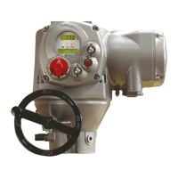
BIFFI F01-2000 ELECTRIC ACTUATOR
INSTRUCTION AND OPERATING MANUAL
The curves below may better clarify the above
option:
Example A
With input signal = 4 mA, the position request
is 0% and the actuator is driven to close. With
input signal = 20 mA, the position request is
100% and the actuator is driven to open. With
input signal = 12 mA the position request
is 50% and the actuator is driven to reach
position 50%.
Example B
With input signal < 8 mA, the position request
is 0% and the actuator is driven to close. With
input signal = 16 mA, the position request is
100% and the actuator is driven to open. With
input signal = 12 mA the position request
is 50% and the actuator is driven to reach
position 50%.
Example C
With input signal = 4 mA , the position request
is 100% and the actuator is driven to open. With
input signal = 20 mA, the position request is 0%
and the actuator is driven to close. With input
signal = 12 mA the position request is 50% and
the actuator is driven to reach position 50%.
Example D
With input signal < 8 mA, the position request
is 100% and the actuator is driven to open. With
input signal = 16 mA , the position request is 0%
and the actuator is driven to close. With input
signal = 12 mA the position request is 50% and
the actuator is driven to reach position 50%.
EXAMPLE A
Position request %
Input signal
4 20 mA
Configured values:
% min = 0%
% max = 100%
Polarity : 4 mA = CL
EXAMPLE B
Position request %
Input signal
4 8 16 20 mA
Configured values:
% min = 25%
% max = 75%
Polarity : 4 mA = CL
EXAMPLE C
Position request %
Input signal
4 20 mA
Configured values:
% min = 0%
% max = 100%
Polarity : 4 mA = OP
EXAMPLE D
Position request %
Input signal
4 8 16 20 mA
Configured values:
% min = 25%
% max = 75%
Polarity : 4 mA = OP
Configuration procedure
• Move the local selector to OFF and then
simultaneously press OPEN and STOP. Select
the language and then enter the password
according to the instructions (see Entering
the set-up mode). When the message
displayed is “SET-UP MODE OK?” press
YES. Press YES to select the actuator set-up
menu, press NO to scroll the list of available
routines and then press YES to select
POSITIONER.
• Press YES if the configured value of the
Dead Band is correct (from “position
resolution %” to 25.5%), or press NO to
change it, then press YES.
• Press YES if the configured value of the
Polarity is correct (4 mA=CL or 4 mA=OP), or
press NO to change it, then press YES.
• Press YES if the configured value of the
Motion Inhibit Time is correct (from 1 to
255 sec), or press NO to change it, then
press YES.
• Press YES if the configured value of the
% MIN is correct (from 0 to 75%), or press NO
to change it, then press YES. The standard
value is 0.
• Press YES if the configured value of the
% MAX is correct (from 25 to 100%), or
press NO to change it, then press YES. The
difference between % MAX and % MIN should
be greater than 25%. The standard value
is 100.
9�1�8 Fail Safe
This function configures the actuator action in
case of loss of the 4-20 mA input or bus signals.
This action only takes place if the local selector
is in REMOTE and if the positioning function
or the bus interface are active. When the
4-20 mA or bus signal is restored, the F01-2000
resumes its normal functioning. The Interlock
and ESD controls override the Fail Safe action
according to the following diagram:
OP/CL controls
Lowest priority Highest priority
Fail Safe action Interlocks ESD
The following options can be configured:
- Action: open, close, stay-put, go to position %,
no action (OFF).
- Delay: time before than the Fail Safe action
takes place.

 Loading...