42
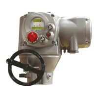
BIFFI F01-2000 ELECTRIC ACTUATOR
INSTRUCTION AND OPERATING MANUAL
Opening time This datum is only available in the general data log. It is updated at the end of every
full valve stroke of the valve in opening direction. The data of the previous stroke are
lost. It gives the time necessary to the valve to move from the close position to the open
position, expressed in hours, minutes and seconds.
Closing time This datum is only available in the general data log. It is updated at the end of every full
valve stroke of the valve in closing direction. The data of the previous stroke are lost.
It gives the time necessary to the valve to move from the open position to the close
position, expressed in hours, minutes and seconds.
Contactor cycles This number counts the cycles of contactors K1 and K2. The value indicated in the
general data log is also used to generate the “max. contactor cycles” warning when the
maximum allowable number of cycles of the contactor is reached (see paragraph12.10,
Diagnostic messages). If the main power is DC or single phase and in modulating
actuators, the counters (general and recent) are hold to 0.
Motor run time This number counts the hours with motor energized.
No power time This number counts the hours without electrical power.
Utilization rate This number % is incremented every 200 full strokes of the actuator. It reaches 100%
after 20 000 full strokes.
Temperature min This is the lowest temperature value (in °C) measured inside the electronics
compartment.
Temperature max This is the highest temperature value (in °C) measured inside the electronics
compartment.
Term temp min This is the lowest temperature value (in °C) measured inside the terminal board
enclosure.
Term temp max This is the highest temperature value (in °C) measured inside the terminal board
enclosure.
Motor temp max This is the highest temperature value (in °C) measured in the electrical motor.
Thermostat alarms This counts the number of alarms due to the high temperature of the electrical motor
and to the tripping of the motor thermostat.
Torque alarms This counts the number of alarms due to high torque in opening and closing.
10�4�5 Maintenance date
The routine allows viewing the following dates:
- Last date
- Next date
- Start-up date
- Recent log date
(see table below)
View procedure
• Move the local selector to OFF and then
simultaneously press OPEN and STOP. Select
the language according to the instructions
(see “Entering the view mode”). When the
message displayed is “VIEW MODE OK?”
press YES. Press NO to scroll the list of
available menus and press YES to select the
Maintenance menu.
• Press NO to scroll the list of available
routines and press YES to select the
maintenance date routine.
• Press YES to scroll the list of dates.
Last date This is the date of the last maintenance operation. The date should be updated by the user after all maintenance operations (see paragraph 9.3).
Next date This is the date of the next scheduled actuator maintenance. When the date is reached, the F01-2000 generates a maintenance request warning.
Thedate should be updated by the user after all maintenance operations (see paragraph 9.3).
Start-up date This is the date of actuator start-up. During commissioning, the user should enter the start-up date (see paragraph 9.3).
Recent log date This is updated after entering command “Clear recent data log” (see paragraph 9.3). This command clears the “recent data log” counters.
The content of “recent log” is updated starting from “recent log date”.
10�4�6 Data logger
The “data logger” routine allows to collect
different types of data useful in maintenance
or in diagnostic programs. Since the amount of
collected data is very large, the data logger can
only be viewed by means of a PDA or PC. The
data can be up-loaded from F01-2000 to PDA
or PC by the Bluetooth
TM
wireless connection.
The local display only allows to view the
value of the configured parameters (see also
SET-UP menu, Maintenance, Set data logger,
paragraph9.3.7). The following data can be
viewed on the local display:
- Logger mode
- Sampling time
- Memory mode
- Date
- Time
In RECORDER and T-RECORDER mode
the SAMPLING TIME fixes the time interval
among two sets of measures. Up to 256 sets
of measures (equivalent to 256x4 samples)
can be memorized. The sampling time can
be configured from 1 to 3600 secs. As the
memory is full, the recorder stops recording or
overwrites the previous data according to the
selected MEMORY MODE (“stop when full” or
“continuous”). If “continuous” was selected, as
a new set of measures is achieved the oldest
one is cancelled and the new one becomes
the latest. Up to 10000 cycles of full memory
overwriting are done, then the recorder stops.
In T-RECORDER mode, the recording operation
is also stopped in case of OVER-TORQUE
ALARM, in opening or in closing. This additional
feature allows to maintain in the memory the
last 256 samples and see the trend of torque,
motor temperature and main voltage before the
alarm. A new start of T-RECORDER clears the
data stored in the memory. By a PDA or PC the
recorded data can be viewed by a graph where
time is on the X axis and the measured data on
the Y axis.
Data logger modes:
• OFF: the data logger is not active.
• RECORDER mode: the F01-2000 measures
and memorizes the following 3 data:
- Main voltage supply (V)
- Motor temperature (°C)
- Temperature inside the compartment of
electronics (°C)
• T-RECORDER mode: the F01-2000 measures
and memorizes the following 3 data:
- Torque in OP/CL
- Motor temperature (°C)
- Voltage

 Loading...