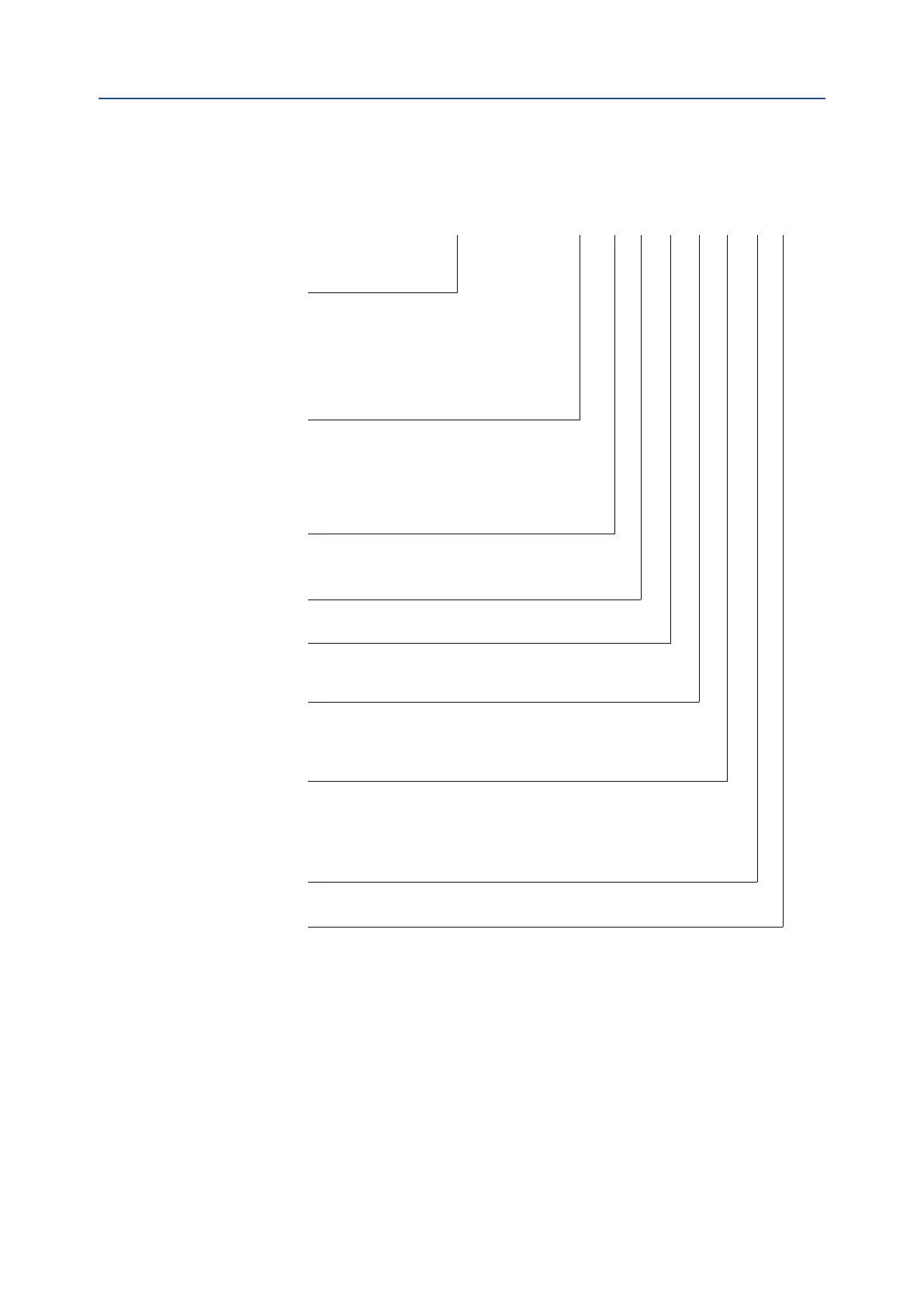
234IMV X1 X2 X3 X4 X5 X6 X7 X8
0) Product Identification (6 Digits)
1) Pressure Sensors configuration (1 Digit)
0 = Sensors [S1] and [S2] not installed
A = Single sensor [S1] 10 barg (145 psig) (*)
B = Double sensors [S1]+[S2] 10 barg (145 psig) (*)
C = Single sensor [S1] 100 barg (1450 psig)
D = Double sensors [S1]+[S2] 100 barg (1450 psig)
E = Single sensor [S1] 200 barg (2900 psig)
F = Double sensors [S1]+[S2] 200 barg (2900 psig)
G = Single sensor [S1] 400 barg (5800 psig) (**)
H = Double sensors [S1]+[S2] 400 barg (5800 psig) (**)
2) Configuration / Wiring Diagram (1 Digit)
A = Configuration A
B = Configuration B
C = Configuration C
D = Configuration D
E = Configuration E
F = Configuration F
G = Configuration G
H = Configuration H
3) Bus/Interface Cards (1 Digit)
0 = Without bus/interface car
ds
1 = HART + 4-20mA Output Interface
2 = MODBUS Interface
3 = HART + 4-20mA Output Interface – IMVS2000 replacement (***)
4) Material (1 Digit)
0 = Full enclosure in SS 316L
1 = Full enclosure in SS 316L + anticorrosive paint (*)
5) Beacon® indicator (1 Digit)
0 = Standard indicator (see 10.3)
1 = Black/Yellow Beacon® indicator
2 = Red/Green Beacon® indicator
6) Additional pressure sensor scale (1 Digit)
0 = Sensor [S3] not installed
1 = Sensor [S3] 10 barg (145 psig) (*)
2 = Sensor [S3] 100 barg (1450 psig)
3 = Sensor [S3] 200 barg (2900 psig)
4 = Sensor [S3] 400 barg (5800 psig) (**)
7) Certification (1 Digit)
0 = ATEX/IECEx (with Standard Indicator: II 2GD Exd IIC T4, with Beacon® Indicator: II 2GD Exd IIB T4)
IP66/68 and NEMA 4, 4X & 6
1 = CCOE - IP66/68 and NEMA 4, 4X & 6
2 = EAC - IP66/68 and NEMA 4, 4X & 6
3 = INMETRO - IP66/68 and NEMA 4, 4X & 6
4 = CSA: see paragraph 2.5.1
5 = CSAus: see paragraph 2.5.1
8) Sha
ft (1 Digit)
B = Shaft Standard Biffi
N = Shaft Namur Type