Installation, Operation and Maintenance Manual
September 2019
MAN720_IMVS2000v2_IOM Rev. 6
Section 5: Working Principle
Working Principle
5.1.7 Opening FST Details
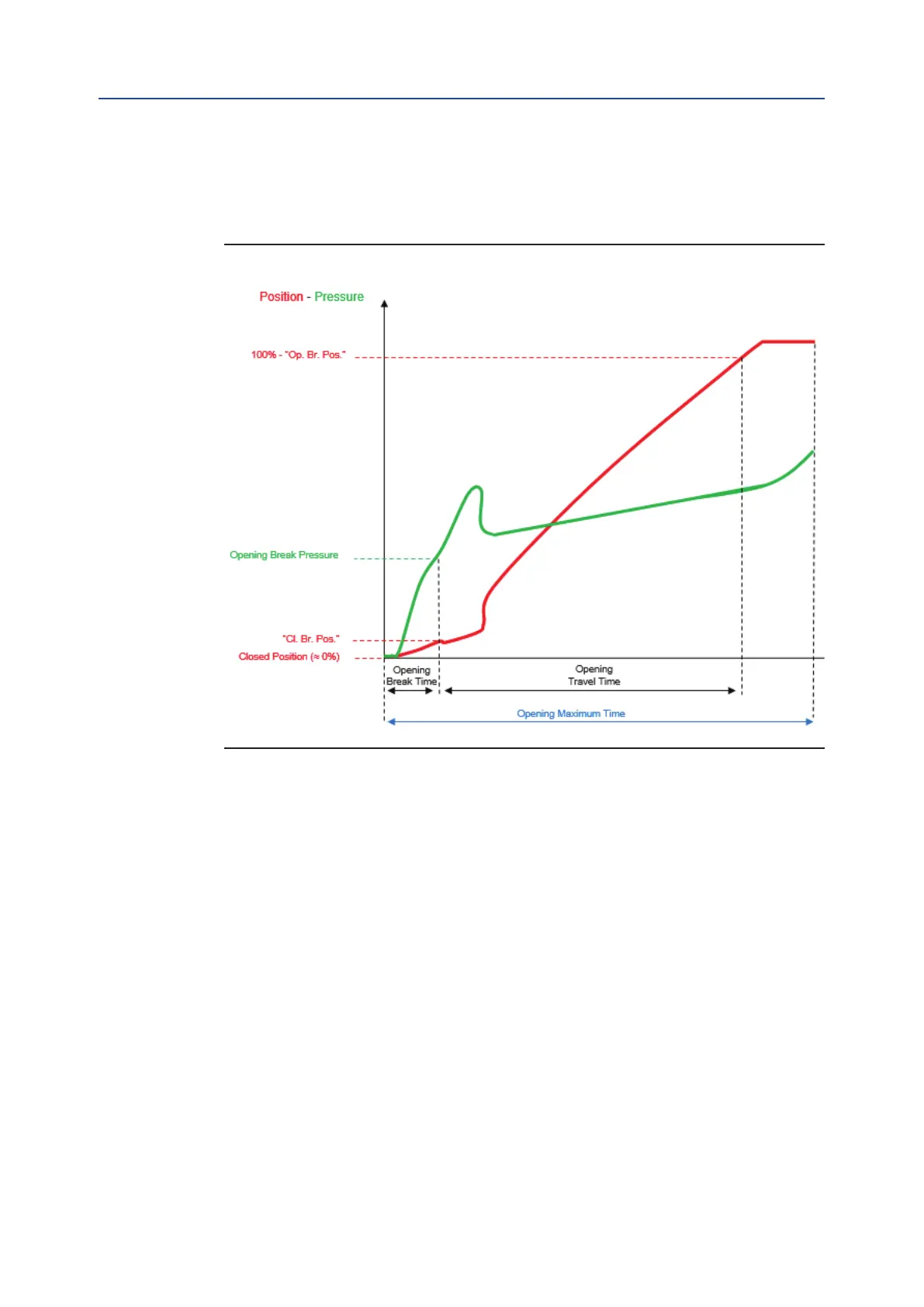
The figure below shows an example of Opening FST.
Figure 5
The position is expressed as % of the Open Position (100% = Open Position, 0% = Closed Position).
The Opening Maximum Time is the total time of the Opening FST Graph. It is automatically calculated by
the IMVS2000v2 (set equal to the Calculated Opening Time). See 5.2.8 for details.
For the Double Acting actuator, the Opening Break Pressure is expressed as the absolute value of the
difference between the Pressure 1 (pressure sensor S1) and the Pressure 2 (pressure sensor S2).
Considering that “Op. Br. Pos” and “Cl.Br. Pos” are fixed to 3%.
• Opening Break Time = time to go from Closed Position to 3%
• Opening Break Pressure = pressure measured at 3%
• Opening Travel Time = time to go from 3% to 97%
If the starting position is not lower than 3% the Closing Break Time, the Closing Travel Time and the Closing
Break Pressure are set to 0. If at the end of the Opening FST the position is lower than 97%, the Opening
Travel Time is set to 0.The OPCT alarm, if enabled, is generated (see Sections 5.2.7 and 8 for details).
The Opening Break Time, the Opening Travel Time and the Opening Break Pressure of the Closing FST of
the Baseline Signature are compared to the ones of the last Closing FST and if they do not respect the set
tolerances, dedicated alarms can be activated (see Sections 5.2.7 and 8 for details).
21