September 2019
Installation, Operation and Maintenance Manual
MAN720_IMVS2000v2_IOM Rev. 6
MAN720_IMVS2000v2_IOM Rev. 6
Section 9: Wiring Diagrams - SIgnals Description
Wiring Diagrams - Signals Descriptions
Section 9: Wiring Diagrams –
Signals Description
9.1 Signals Description
9.1.1 Standard Signals
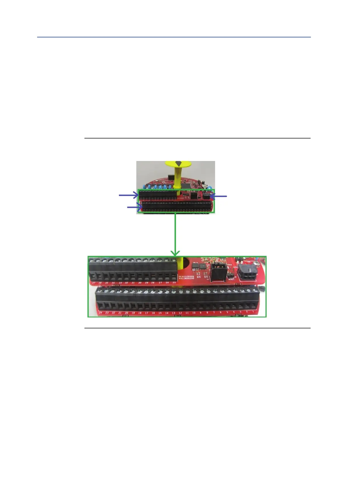
Figure 15
CN20 for cable
connection with
Display Card
Terminals 25-37
(Logic Card)
Terminals 1-24
(Base Power Card)
The previous figure shows the standard terminals (without optional cards) of the IMVS2000v2.
The table below describes the signals of the standard terminals of the IMVS2000v2.
74