Installation, Operation and Maintenance Manual
September 2019
MAN720_IMVS2000v2_IOM Rev. 6
Section 9: Wiring Diagrams - SIgnals Description
Wiring Diagrams - Signals Descriptions
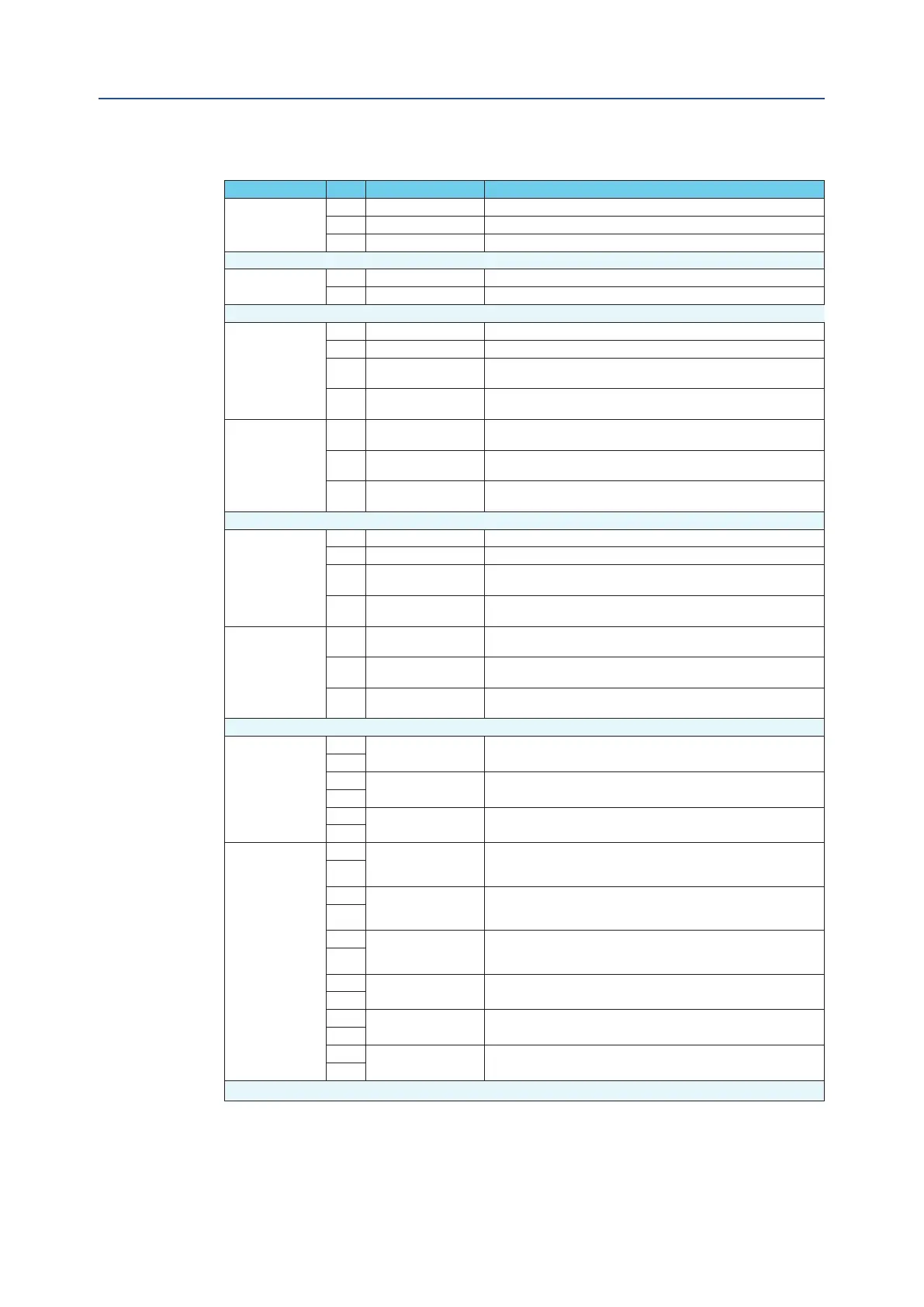
Table 10.
Type # Signal Name Description
EARTH
1 EARTH Protection Earth.
2 EARTH Protection Earth.
37 EARTH Protection Earth.
Main Supply
3 +Vin Positive Input of the power supply of the electronic cards.
4 -Vin Negative Input of the power supply of the electronic cards.
SIS A
5 +SIS A Positive Input of the power supply dedicated to the SOVA.
6 - SIS A Negative Input of the power supply dedicated to the SOVA.
7 + SIS A (aux)
+ SIS A Auxiliary contact used for internal wired connection
(see Section 9.2 for details).
8 -SIS A (aux)
- SIS A Auxiliary contact used for internal wired connection
(see Section 9.2 for details).
SOVA
9 SOV A+(NC)
If used, it must be connected to the positive terminal of the SOVA
(see Section 9.2 for details).
10 SOV A+(NO)
If used, it must be connected to the positive terminal of the SOVA
(see Section 9.2 for details).
11 SOVA-
It must be connected to negative terminal of the SOVA
(see Section 9.2 for details). It is internally connected to – SIS A.
SIS B
12 +SIS B Positive Input of the power supply dedicated to the SOVB.
13 - SIS B Negative Input of the power supply dedicated to the SOVB.
14 + SIS B (aux)
+ SIS B Auxiliary contact used for internal wired connection
(see Section 9.2 for details).
15 -SIS B (aux)
- SIS B Auxiliary contact used for internal wired connection
(see Section 9.2 for details).
SOVB
16 SOV B+(NC)
If used, it must be connected to the positive terminal of the SOVB
(see Section 9.2 for details).
17 SOV B+(NO)
If used, it must be connected to the positive terminal of the SOVB
(see Section 9.2 for details).
18 SOVB-
It must be connected to negative terminal of the SOVB
(see Section 9.2 for details). It is internally connected to – SIS B.
Digital Inputs
19
SOLENOID A CONTROL
It is used for controlling the SOVA. Its functionality depends on the
device conguration (see Section 5.2.2 for details).
20
21
SOLENOID B CONTROL
It is used for controlling or testing (SOV TEST) the SOVB. Its functional-
ity depends on the device conguration (see Section 5.2.2 for details).
22
23
PST CONTROL
It is used for performing a “Manual PST” or a “SOV A TEST” or a “SOV
A – SOV B TEST” (see Section 5.2.2 for details).
24
Digital Outputs
25
OPEN SIGNAL
It is a solid state dry contact associated to the Open Position.
It can be set as Normally Open or Normally Closed
(see Section 5.2.3 for details).
26
27
CLOSE SIGNAL
It is a solid state dry contact associated to the Closed Position.
It can be set as Normally Open or Normally Closed
(see Section 5.2.3 for details).
28
29
COMMON FAILURE
ALARM
It is a solid state dry contact associated to “C.F.A St.”.
It can be set as Normally Open or Normally Closed
(see Section 5.2.3 for details).
30
31
PST IN PROGRESS
It is a solid state dry contact that closes during the PST execution or
during SOVs TEST (see Section 5.2.3 for details).
32
33
PST PASSED
It is a solid state dry contact associated to “PST Status”
(see Section 5.2.3 for details).
34
35
PST FAILED
It is a solid state dry contact associated to “PST Status”
(see Section 5.2.3 for details).
36
75