September 2019
Installation, Operation and Maintenance Manual
MAN720_IMVS2000v2_IOM Rev. 6
MAN720_IMVS2000v2_IOM Rev. 6
Section 5: Working Principle
Working Principle
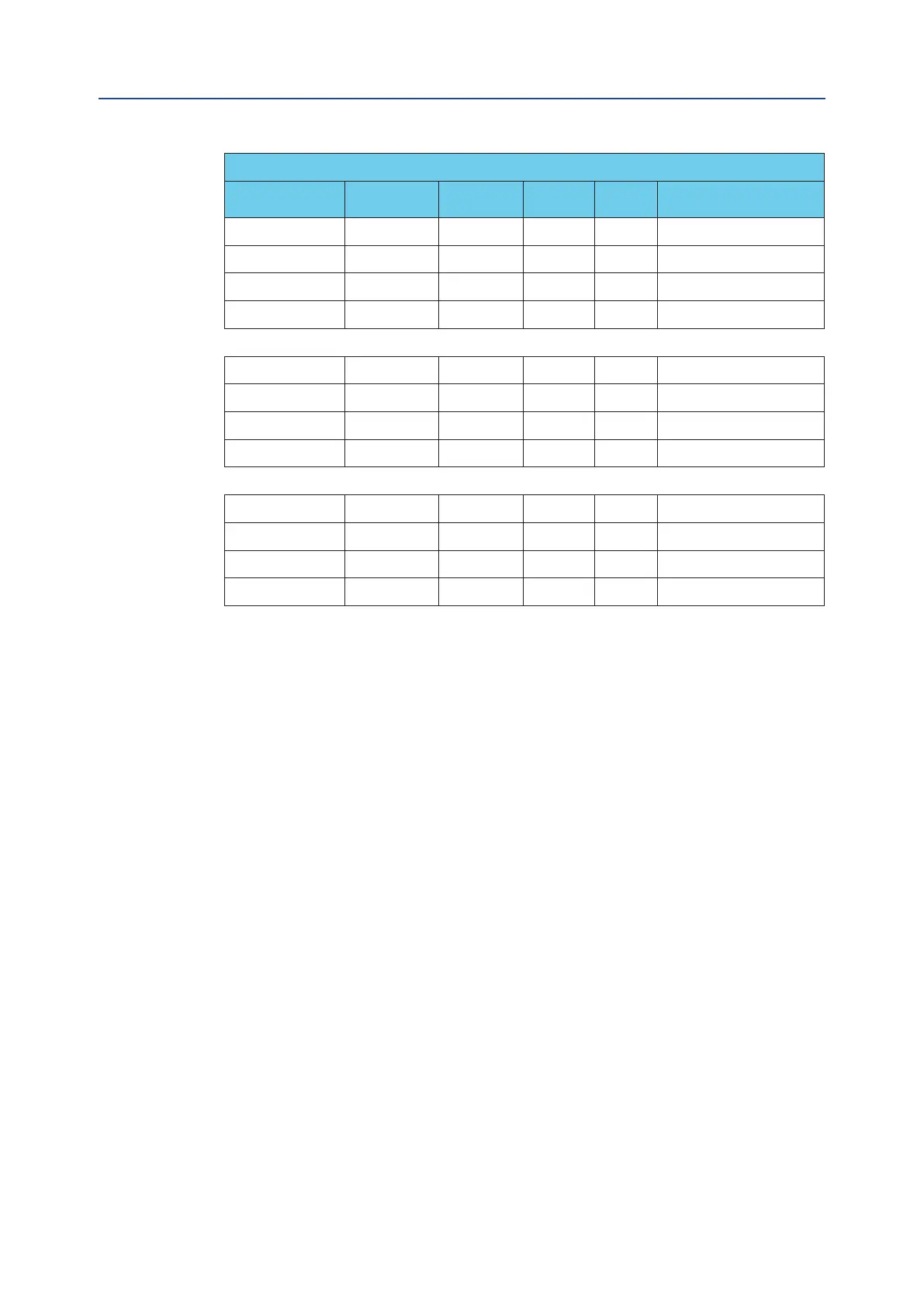
Position Request Table – Digital Inputs
“Act. Mode” “Fail Action” “SOVs Qty”
SOV A
CTRL
SOV B
CTRL
“Position Request” (*)
Single or Double-S OP Series Active Active 0%
Single or Double-S OP Series Not Active Active 100%
Single or Double-S OP Series Active Not Active 100%
Single or Double-S OP Series Not Active Not Active 100%
Single or Double-S OP Parallel Active Active 0%
Single or Double-S OP Parallel Not Active Active 0%
Single or Double-S OP Parallel Active Not Active 0%
Single or Double-S OP Parallel Not Active Not Active 100%
Double - - Active Not Active 100%
Double - - Not Active Active 0%
Double - - Not Active Not Active Last “Position Request”
Double - - Active Active 100%
5.2.3 Digital Output
The IMVS2000v2 is provided with 6 Digital Outputs (DO).
- OPEN
- CLOSED
- COMMON FAILURE ALARM
- PST IN PROGRESS
- PST PASSED
- PST FAILED
Each DO is isolated from the other ones and can work with the following voltages:
• Up to 57.6 Vdc – 0.5 A
They are SPST solid state dry contacts. When the IMVS2000v2 is not power supplied the DOs are all
open contacts.
The OPEN, CLOSED and COMMON FAILURE ALARM digital outputs can be congured to work as
normally open or normally closed contacts (see Section 5.2.3.1 for details).
5.2.3.1 Digital Outputs Table
See Section 6 for details about the conguration parameters.
34