Installation, Operation and Maintenance Manual
September 2019
MAN720_IMVS2000v2_IOM Rev. 6
Section 5: Working Principle
Working Principle
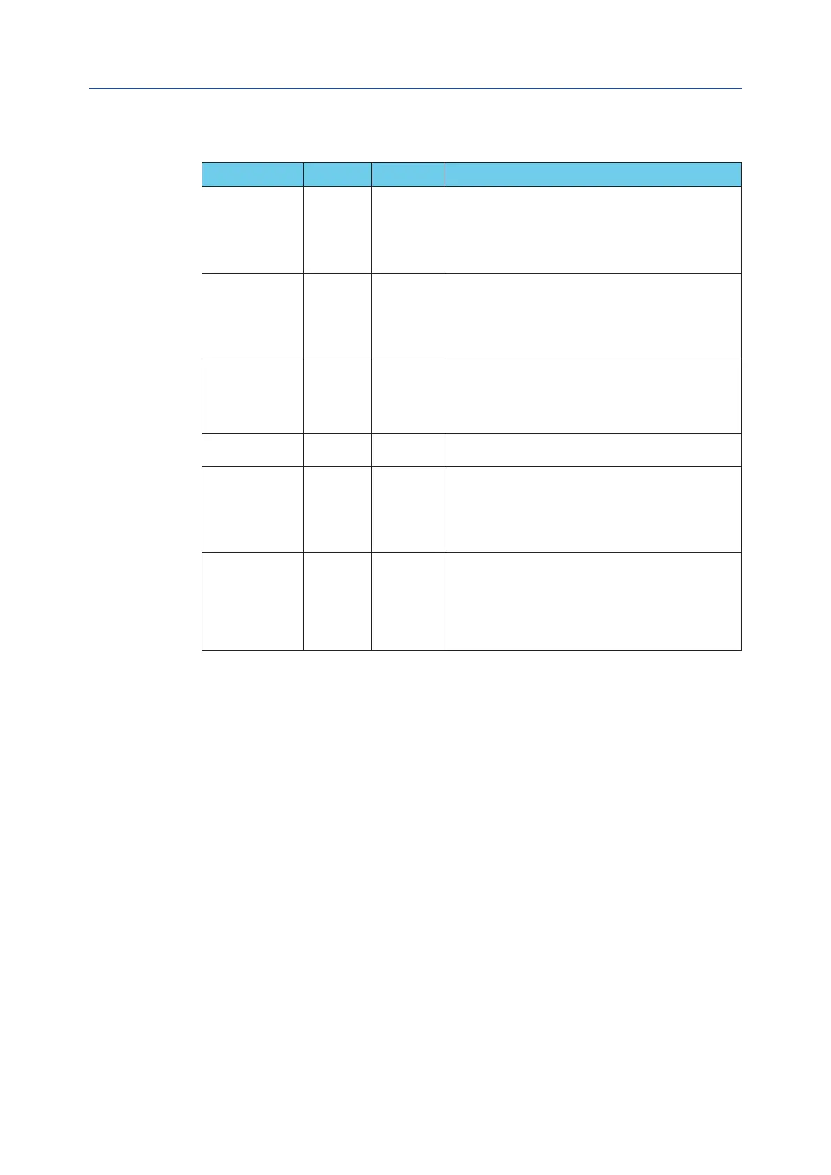
Table 4.
Name Terminals # Type Description (*)
OPEN 25-26 Digital Output
It is a solid state dry contact.
If “Op. Cl. Mode” = “NO” (default setting):
The contact is closed when the Fully Open Position is reached (accord-
ing to the set “Open Position Hysteresis.”)
If “Op. Cl. Mode” = “NC”:
The contact is open when the Fully Open Position is reached (accord-
ing to the set “Open Position Hysteresis.”)
CLOSED 27-28 Digital Output
It is a solid state dry contact.
If “Op. Cl. Mode” = “NO” (default setting):
The contact is closed when the Fully Closed Position is reached (ac-
cording to the set “Closed Position Hysteresis.”)
If “Op. Cl. Mode” = “NC”:
The contact is open when the Fully Closed Position is reached (accord-
ing to the set “Closed Position Hysteresis.”)
COMMON FAIL-
URE ALARM
29-30
Digital Output
It is a solid state dry contact.
If “Co. Fail Alr mode” = “NO”
The contact is closed when “CFA St.” = “Active”.
If “Co. Fail Alr mode” = “NC”
The contact is open when “CFA St.” = “Active”.
See 6 for details.
PST IN PROGRESS 31-32 Digital Output
It is a solid state dry contact that is closed during the PST execution
(both Baseline PST and Manual PST) and the SOV TEST.
PST PASSED 33-34 Digital Output
It is a solid state dry contact that depends on the value of “PST
Status”:
“PST Status” = “Passed” => contact closed
“PST Status” = “Failed, “Not Done”, “Conf. Err” => contact open
“PST Status” = “Progress” => contact closed. (*)
It is updated at the end of each PST or SOV Test.
See 6 for details.
PST FAILED 35-36 Digital Output
It is a solid state dry contact that depends on the value of “PST
Status”:
“PST Status” = “Passed” => contact open
“PST Status” = “Failed, “Conf. Err” => contact closed
“PST Status” = “Not Done” => contact open.
“PST Status” = “Progress” => contact closed (*)
It is updated at the end of each PST or SOV Test.
See 6 for details.
Notes:
(*) During the SOV TEST, the “PST Status” = “Progress” but this contact remains at its present
status without changing.
5.2.4 SIS Signals - SOV Outputs
Refer to the paragraph 9 for seeing the typical wiring diagrams of the IMVS2000v2.
The IMVS2000v2 is provided with two independent (isolated) circuits for controlling up to two
external Solenoid Valves (SOVA and SOVB).
Each circuit has its own dedicated power supply (SIS A and SIS B) that through a relay is used to
control the SOVA and SOVB (see 9 for details).
Both SIS A and SIS B power supply are continuously monitored and dedicated alarms can be
generated (see Section 5.2.7 for details).
If the SIS A signal is not applied the IMVS2000v2 cannot energize the SOVA; when the SIS A is
removed the SOVA is “automatically” de-energized.
If the SIS B signal is not applied the IMVS2000v2 cannot energize the SOVB; when the SIS B is
removed the SOVB is “automatically” de-energized.
5.2.5 Position Sensor
The IMVS2000v2 is provided with an internal contactless position sensor. The position can be read on
the shaft that is connected to the actuator.
The accuracy of the Position Sensor is 0.2%.
35