Installation, Operation and Maintenance Manual
September 2019
MAN720_IMVS2000v2_IOM Rev. 6
Section 5: Working Principle
Working Principle
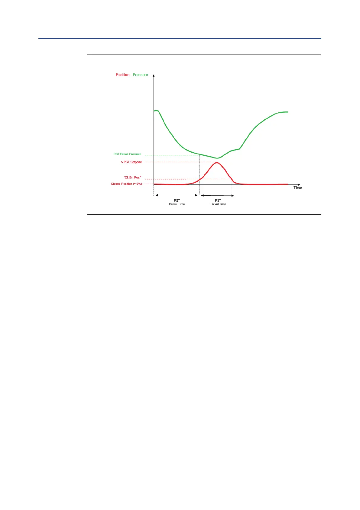
Figure 7
The position is expressed as % of the Open Position (100% = Open Position, 0% = Closed Position).
The PST Maximum Time is the total time of the PST Graph. It is automatically calculated by the
IMVS2000v2 (set equal to the Calculated PST Time). See Section 5.2.8 for details.
For the Double Acting actuator, the Opening Break Pressure is expressed as the absolute value of the
difference between the Pressure 1 (pressure sensor S1) and the Pressure 2 (pressure sensor S2).
Considering that “Op. Br. Pos” and “Cl.Br. Pos” are fixed to 3%.
• PST Break Time = time to go from Closed Position to 3%
• PST Break Pressure = pressure measured at 3%
• PST Travel Time = time to go from 3% to 3%, passing for the setpoint
If the starting position is not lower than 3% the PST Break Time, the PST Travel Time and the PST
Break Pressure are set to 0. If at the end of the PST the position is higher than 3%, the PST Travel Time
is set to 0. The PSCT alarm, if enabled, is generated (see Sections 5.2.7 and 8 for details).
The PST Break Time, the PST Travel Time and the PST Break Pressure of the Baseline PST are
compared to the ones of the last Manual PST and if they do not respect the set tolerances, dedicated
alarms can be activated (see Sections Sections 5.2.7 and 8 for details).
The Partial Closing Stroke can be performed only if the actuator is closed and if the IMVS2000v2 is
configured as fail to open (“Fail Mode” = “OP”).
5.1.8.1 PST + SOV TEST Details
The figure below shows an example of Partial Closing Stroke on a system with two SOVs in series (see
for example Configuration C on paragraph 9.2.3) where one SOV is used to perform the PST and the
other SOV is tested through a SOV TEST.
This kind of test is performed in case of the following settings (see 5.1.6):
• “Act. Mode” = “Single” or “Double-S”
• “SOVs Qty” = “Series”
• “PST Ser. SOVs” = “Both”
• "Pr. S. 1-2" ≠ “None”
23