KBF / KBF P (E5.2) 02/2012 page 65/103
12. Humidity system
The humidity system is turned on with the humidity switch (4) located in the right lateral control panel.
The climatic chamber KBF / KBF P is equipped with a capacitive humidity sensor. This results in a control
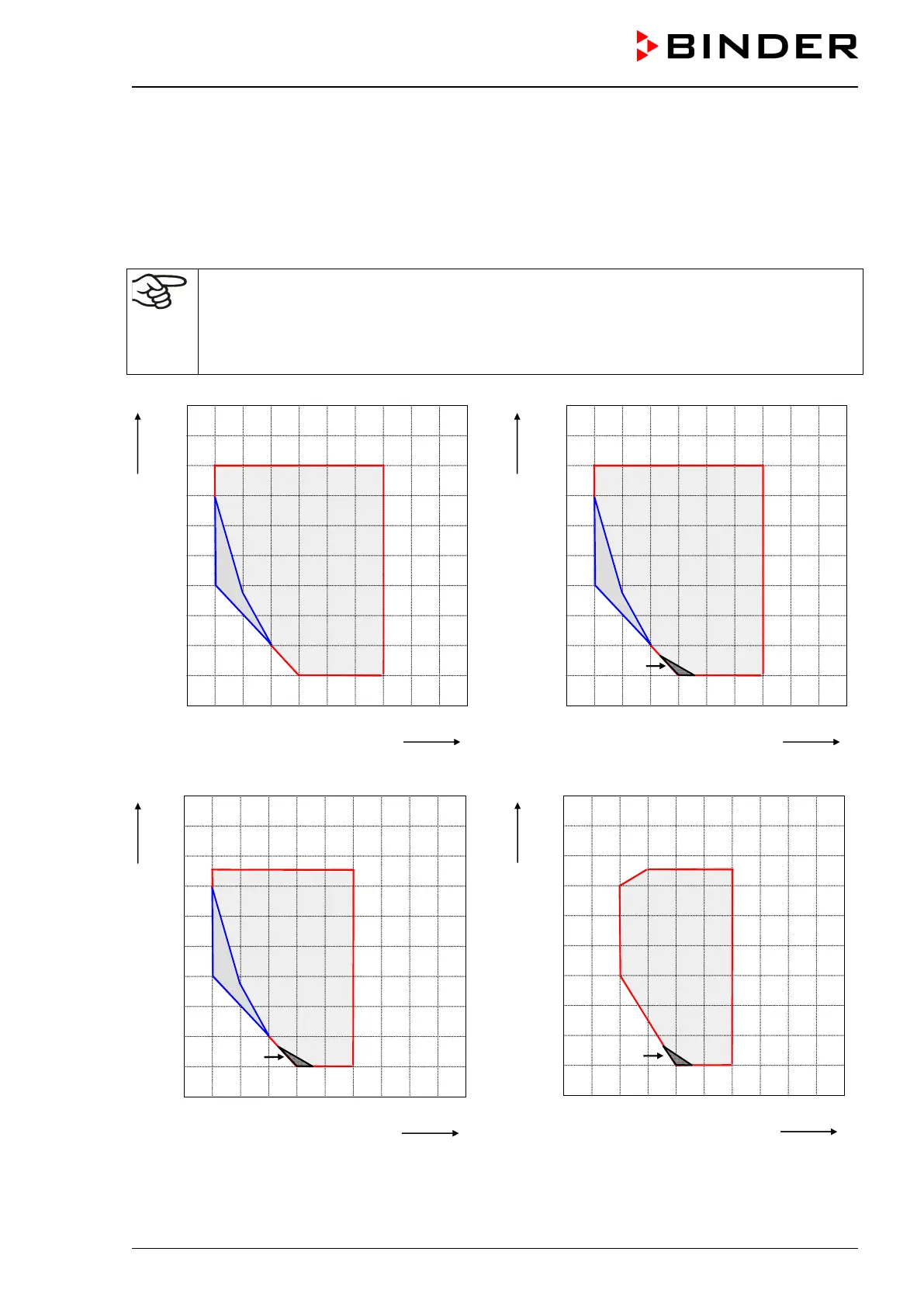
accuracy of up to ± 3 % r.H. of the set point. The temperature-humidity diagrams (Figure 21) show the
possible working ranges for humidity.
The preset temperature and humidity values should be situated within the optimum range
(hatched range in Figure 21). Only within this area will the unit not be expose
moisture due to condensation.
In the short-term set points outside the optimum range can also be targeted. The control accu-
racies of ± 3 % r.H., however, cannot be guaranteed in this case.
KBF KBF P without light cassettes
KBF P 240 with illumination KBF P 720 with illumination
Figure 21: Temperature-Humidity diagrams