KBF / KBF P (E5.2) 02/2012 page 71/103
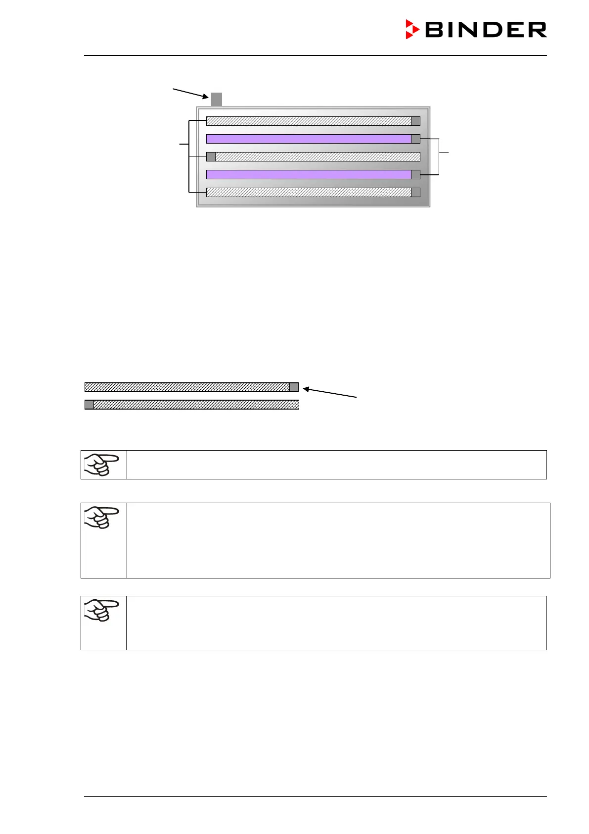
Figure 24: Arrangement of the fluorescent tubes in the light cassette
The fluorescent tubes are turned on by two additional switches (10) and (11) on the left lateral control
panel (switches in position “I“).
(10) Switch for ICH compliant illumination BINDER Q1B Synergy Light (light color 640 cool white and
UVA)
(11) Switch for ICH compliant illumination cool white (light color 640)
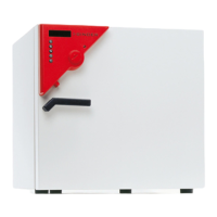
You will obtain optimum homogeneity by alternately placing the fluorescent tubes of the same type, i.e.,
opposite arrangement of the inscription:
Inscription
Figure 25: Opposite arrangement of two fluorescent tubes
When replacing the fluorescent tubes, observe tube orientation (inscription).
How to replace the fluorescent tubes is described in chap.16.2.
Operation with light cassettes and illumination on: Maximum temperature 60 °C / 140 °F.
Operation with light cassettes and illumination off: Do also NOT operate the unit at tempera-
tures >60 °C / 140 °F. Otherwise, the lifetime of the fluorescent tubes will be considerably re-
duced.
When operating the chamber at temperatures > 60 °C / 140 °F, remove the light cassettes.
Entering the set point values for KBF P when operating without illumination:
• Adapt the setting of the temperature set-point according to the table in chap. 8.2.
• Adapt the setting of the humidity set-point according to the table in chap. 8.2.