3. Using the numeric keypad or the voltage adjust rotary knob, enter a voltage value. The
voltage display will now show the value you entered. If entering with numeric keypad,
press the button first, then enter the value and press the button.
4. If the button is not already illuminated, press it once to display the measured
voltage at the output. The voltage may fluctuate slightly from the value entered in the
previous step.
5. (Optional) You may also verify the output voltage by connecting the (+) and (-) terminals to
an external voltmeter. The measured value should match or be comparable to the entered
voltage value.
6. Check the other two channels following the same procedure.
Current Check
Follow the steps below to check current output of the power supply.
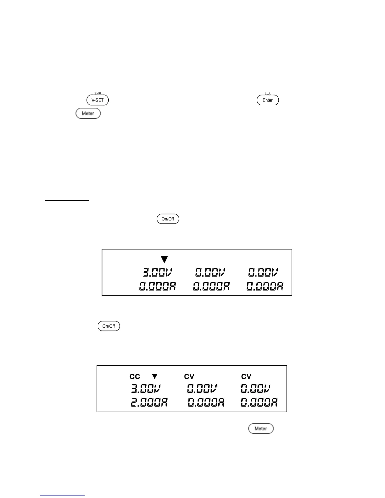
1. Turn off all output channels ( button will not be illuminated).
2. Short the (+) and (-) output terminals with test leads or a shorting bar.
3. Adjust the voltage value of Channel 1 to 3V.
4. Press the button to enable the output. The CV indicator will change immediately
to CC indicating the power supply is in constant current mode. The CC mode allows the
supply to adjust the current output. The voltage automatically adjusts to maintain the
relationship of current, voltage and resistance according to Ohm’s Law.
Figure 10 - VFD display: Outputs of Power Supply disabled. Channel 1 selected.
5. Set different current values between 0A and 3A. Press the button and observe
how the voltage value on the VFD is approximately 0 volts.
Figure 9 – VFD display: Outputs of Power Supply disabled. Channel 1 selected.
www.GlobalTestSupply.com
Find Quality Products Online at: sales@GlobalTestSupply.com