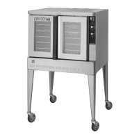
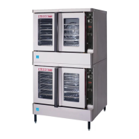
MARK V
2-21
BLODGETT IQ CONTROL - 33078 REV A
Component Reference
NOTE: Refer to FIGURE 10 page 2-22 for compoĆ
nent locations.
1. POWER SWITCH
2. STEP DOWN TRANSFORMER
3. RELAY BOARD
4. AXIAL FAN
5. COMPUTER
6. TEMPERATURE PROBE
7. ELEMENT CONTACTOR
8. HEATING ELEMENTS
9. CONVECTION FAN MOTOR
10. DOOR SWITCH
Operation
1. Toggle the power switch (1) to the on position.
Power goes to the primary side of a 208/24 volt
step down transformer (2), terminal #2 of K1 of
the relay board (3), terminal #4 of K2 of the
relay board, terminal #7 of K3 of the relay
board and the axial fan (4).
2. On a call for heat from the computer (5) as
sensed by the temperature probe (6), the coil
of K1 powers up closing the contacts between
terminals #2 and #1 of K1 on the relay board
(3). The coil of the element contacator (7) powĆ
ers up. When the contactor closes the heating
elements (8) power up.
3. The speed of the convection fan motor (9) is
determined by the program in the computer
(5). The computer either closes K2 for high
speed or K3 for low speed.
4. When the doors are closed the door switch
(10) is activated. The computer closes relays
K1, K2 and K3. If the doors are open or the
switch is broken these relays drop out and the
LED displays door.
NOTE: This oven may be converted from single to
three phase, however, contactors must be
changed due to the difference in amp
draw. Reference detail inset in FIGURE 10.
NOTE: The resistive values for the probes used in
this oven have descending temperature
coefficients. As the temperature increases
the resistive values decrease
NOTE: Reference page 4-2 of the TroubleshootĆ
ing section for the reistive values of the
heating elements. The reading should be
taken in a cold state.
 Loading...

