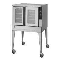
MARK V
2-1
SEQUENCE OF OPERATIONS
NOTE: The following instructions represent the most common controllers. For questions regarding other
options call the Blodgett Service Department at (800)331Ć5842.
COOK ONLY - 18459 REV D
Component Reference
NOTE: Refer to FIGURE 1 page 2-2 for compoĆ
nent locations.
1. MODE SELECTOR SWITCH
2. COOK TIMER
3. DOOR SWITCH
4. TEMPERATURE CONTROL BOARD
5. AXIAL FAN
6. CONV ECTION FAN MOTOR
7. TEMPERATURE PROBE
8. SOLID STATE POTENTIOMETER
9. CENTRIFUGAL SWITCH
10. COOK LIGHT
11. ELEMENT CONTACTOR
12. HEATING ELEMENTS
13. 50 WATT LAMPS
14. LIGHT SWITCH
15. TIMER MOTOR
16. BUZZER
Operation
1. Turn the mode selector switch (1) to the cook
position. Power goes to terminal #1 of the
cook timer (2), one side of the door switch (3),
terminal #8 of the temperature control board
(4) and the axial fan (5).
2. If the doors are closed the door switch (3)
should also be closed sending power to termiĆ
nal #6 of the temperature control board (4)
and to the convection fan motor (6).
NOTE: This motor has a built in centrifugal
switch (9) that closes when the motor
reaches full speed. If found faulty do
not bypass, the whole motor should be
replaced.
3. On a call for heat from the temperature control
circuit, a circuit is completed between termiĆ
nals #6 and #7 of the temperature control
board (4).
NOTE: The temperature control circuit conĆ
sists of the temperature probe (7), the
temperature control board (4) and the
solid state potentiometer (8).
Power is sent out of terminal #7 to one side of
the centrifugal switch (9). If the convection fan
motor (6) is at full speed the centrifugal switch
(9) closes sending power to the cook light (10)
and one side of the element contactor (11).
When the contactor closes the heating eleĆ
ments (12) power up.
4. The 50 watt lamps (13) only receive power when
the light switch (14) is activated. These lamps
are 115 volt and are wired in series parallel.
5. When the cook timer (2) is set for a time a cirĆ
cuit is made between terminals #1 and #2
powering up the timer motor (15). At the expiĆ
ration of the set time the switch in the cook timĆ
er (2) toggles from 1-2 to 1-4 powering up
the buzzer (16).
NOTE: Put the timer in the home position to siĆ
lence the buzzer.
NOTE: Turn the mode selector switch to cool
down to bypass the door microswitch. This
allows the convection fan motor to operate
even when the doors are open.
NOTE: This oven may be converted from single to
three phase, however, contactors must be
changed due to the difference in amp
draw. Reference detail inset in FIGURE 1.
NOTE: The resistive values for the probes used in
this oven have descending temperature
coefficients. As the temperature increases
the resistive values decrease.
NOTE: Reference page 4-2 of the TroubleshootĆ
ing section for the resistive values of the
heating elements. The reading should be
taken in a cold state.
 Loading...

