PARTS REPLACEMENT
5-4
ELECTRICAL COMPONENTS
NOTE: A test cord is available to allow removal of
the control module from the oven while reĆ
taining electrical connections.
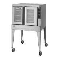
BULB AND CAPILLARY THERMOSTAT
1. Remove the chain and turnbuckle compartĆ
ment cover.
2. Remove the control compartment cover.
3. Remove the racks.
4. Remove the thermostat capillary bulb clips.
5. Swing the capillary bulb forward until it is at a
90_ angle with the liner side.
6. Close the doors. Pull the control module forĆ
ward.
7. Remove the wires from the thermostat.
8. Loosen the set screw at the bottom of the therĆ
mostat knob. Remove the knob.
9. Remove the two (2) screws securing the therĆ
mostat to the front panel.
10. Feed the capillaries through the oven wall and
the side of the control module.
11. Remove the thermostat.
12. Reverse steps 1-11 to replace.
NOTE: Be careful not to kink the fine tubing of the
thermostat capillary.
Capillary
Tube
FIGURE 4
ELECTRICAL COMPONENTS LOCATED
IN THE CONTROL MODULE
1. Remove the chain and turnbuckle compartĆ
ment cover.
2. Remove the control compartment cover.
3. Close the doors. Pull the control module forĆ
ward.
4. Remove the wires from the defective compoĆ
nent.
5. Loosen the screws attaching the component
to the control module.
Switches may be removed by depressing the
spring loaded clips.
The one hour timer is removed by loosening
the locknut.
6. Reverse steps 1-5 to replace.
NOTE: Refer to the wiring diagram to ensure corĆ
rect connection of the wires.
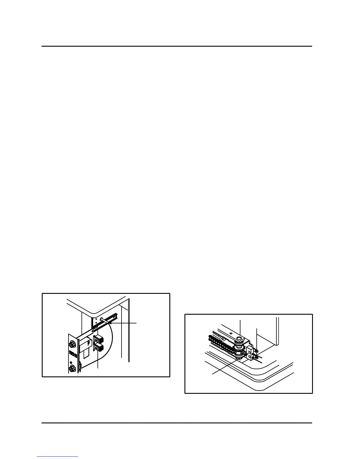
DOOR SWITCH
1. Remove the lower trim cover.
2. Loosen the cam assembly set screw on the
right door sprocket assembly.
3. Remove the wires from the door switch.
4. Loosen the lock nut securing the door switch
to the bracket and remove.
5. Reverse steps 1-4 to replace.
Micro Switch
FIGURE 5