7.0 Maintenance and Adjustments
Your Lemur-FDIO flight strip printer is solidly constructed and has been designed for high volume
use. It requires minimal care to provide maximum service.
WARNING: The appearance of this symbol indicates the proximity of an
exposed high voltage area. Please follow all directions carefully for your
personal safety. You must read the following safety information carefully
before working on the printer.
This section provides an overview of printer maintenance, including part alignments, adjustment and replacement.
For discussion purposes, the printer consists of three major modules or assemblies:
• Paper guide and print head assembly
• Cutter assembly
• Logic board assembly
As a safety precaution, all service to the printer should be done by qualified persons with
power off and the AC cord unplugged from the printer. Following any procedure requiring the
removal of covers and/or doors, please verify that they have been properly attached and
fastened prior to operating the printer.
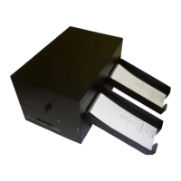
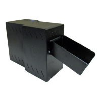
7.1 Paper Guide and Print Head Assembly
The principal function of this assembly is to guide the flight strip stock to the thermal print head where
thermal printing takes place. Additionally, this assembly houses the drive platen and flight strip
positioning sensors. If necessary, the total assembly may be removed from the unit. All replacements
and adjustments of the components on this assembly may be done without removing the total
assembly. The most common adjustments and replacements regarding this assembly follow: