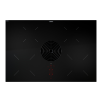
Securing the cooktop
1
2
3
Fig. 6.31 Securing the cooktop in the middle
[1] Cooktop
[2] Installation clamp
[3] Fixing bracket
Secure the cooktop to the worktop [1] with the fixing
bracket [3] on the installation clamp [2] .
Tightening torque: max. 2.2 Nm.
Inserting the grease filter and air inlet nozzle
Next, insert the stainless steel grease filter and the air
inlet nozzle.
Connecting the device to the duct system
INFO The duct system must be fitted to the device free
of load and with the power supply switched off.
INFO For correct installation, the slide-in units of the
base cabinet must be shortened depending on the
installation situation.
INFO When attaching the seals, ensure that an airtight
seal is created with the connection duct piece
when the seals are compressed.
The maximum exhaust air duct length is 6 m.
The minimum cross-section of the air ducts must
be 176 cm², which equates to a round pipe with
a diameter of 150 mm or the BORA Ecotube duct
system.
Use only BORA Ecotube duct parts.
Do not use flexible or fabric hoses.
Before inserting the cooktop, remove the air inlet
nozzle [3] and the stainless steel grease filter [4].
Use the inlet opening [2] as a handle during insertion.
Keep the cooktop [1] straight as you lift it into the
worktop cut-out [5]
Insert the cooktop [1] into the centre of the worktop
cut-out [5].
Precisely align the cooktop.
Information regarding flush installation:
Make sure that the sealing tape of the cooktop is well
sealed all the way round.
Information regarding surface mounting:
Make sure that the sealing tape for the cooktop is flat
against the worktop.
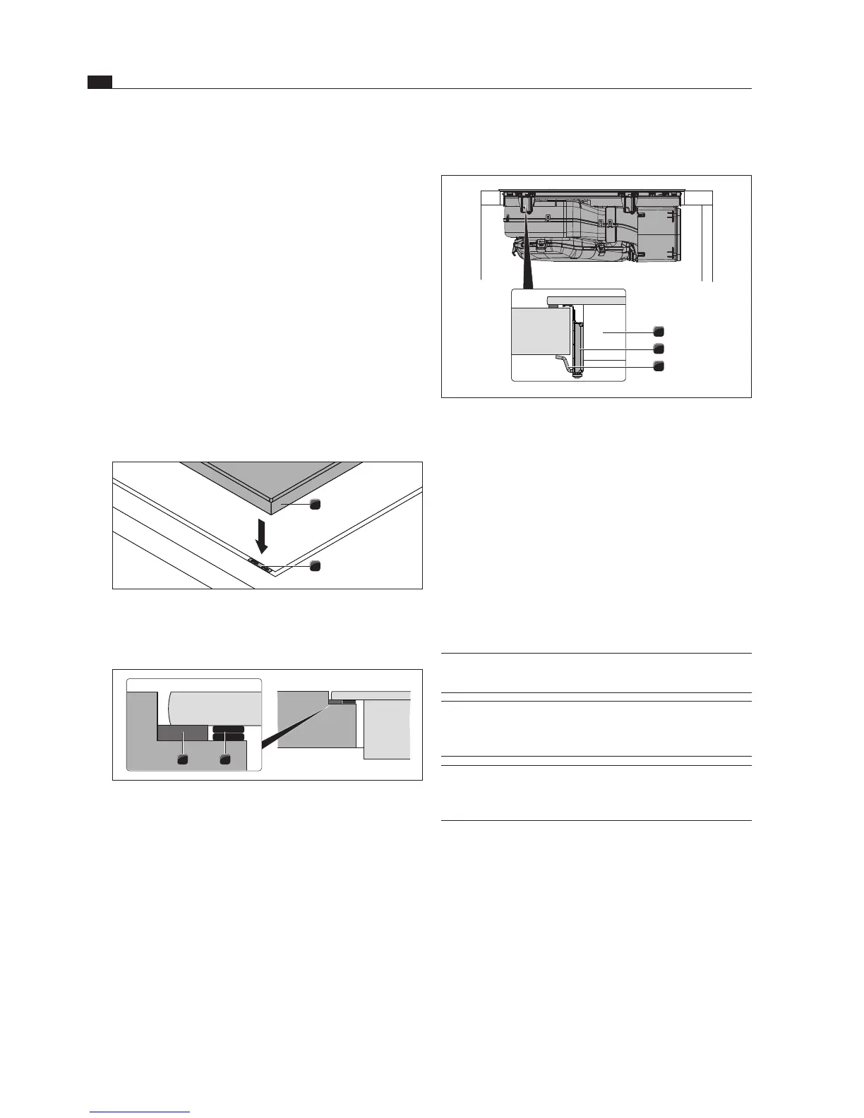
Height adjustment plates for flush
installation(optional)
2
Fig. 6.29 Inserting height adjustment plates
[1] Cooktop
[2] Height adjustment plate
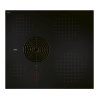
1 2
Fig. 6.30 Height adjustment plates
[1] Sealing tape
[2] Optional height adjustment plates
If necessary, lay the height adjustment plates [2]
underneath.
Place the height adjustment plates next to the sealing
tape [2].