Connection Fuse protection Minimum cross-section
3-phase connection 3 x 16 A 2.5 mm
2
2-phase connection 2 x 16 A 2.5 mm
2
1-phase connection 1 x 32 A 4 mm
2
Tab. 6.3 Fuse protection and minimum cross-section
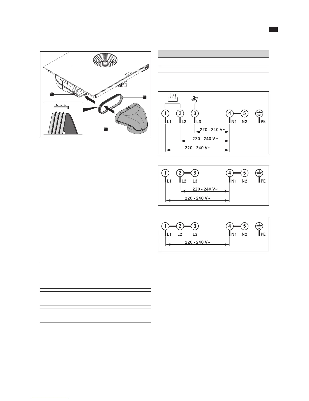
Fig. 6.33 Connection diagram 3-phase connection
Fig. 6.34 Connection diagram 2-phase connection
Fig. 6.35 Connection diagram 1-phase connection
1
3
2
Fig. 6.32 Connecting the duct system
[1] Seal
[2] Duct part
[3] Exhaust opening
Pull the seal [1] onto the exhaust opening [3] on the
device. The seal [1] will need to be stretched slightly.
Push the duct part to be connected [2] with the
coupling onto the exhaust opening [3] with the seal [1].
Ensure that the seal [1] is not displaced.
6.8 Establishing the power
connection
Observe all safety and warning information (see the
Safety chapter).
Observe all national and regional laws and regulations
as well as the supplementary regulations of the local
utility companies.
INFO The power connection may only be established by
certified specialists. The specialist also assumes
responsibility for the proper installation and
commissioning.
INFO Connections via plug-in contacts (Schuko plugs)
are not permitted.
INFO 1-phase connection The device complies with the
requirements of IEC 61000-3-12.
Switch off the main switch/automatic circuit breaker
before connecting the cooktop.
Secure the main switch/automatic circuit breaker
against being switched back on without permission.
Make sure the power to the appliance is disconnected.
Connect the cooktop exclusively via a fixed
connection to an H 05 VV-F power supply cable with
corresponding minimum cross-section (see tab. Fuse
protection and minimum cross-section).