3
2
1
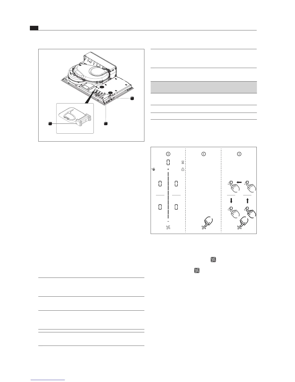
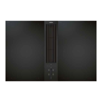
Fig. 6.36 Electrical connections of the cooktop
[1] Power supply
[2] Power supply cover
[3] Mounting eyes
Connect the power supply cable to the power supply
[1] of the device in accordance with the relevant
connection diagram (see Abb. Connection diagram).
For a 1-phase or 2-phase connection, connect the
relevant contacts using the bridge provided (in scope
of delivery).
Secure the connection cable with the strain relief
clamp (in scope of delivery).
Close the power supply housing with the power supply
cover [2] (in scope of delivery).
Lay the connection cable along the mounting eyes [3]
with the help of the cable ties (in scope of delivery).
Ensure that the cable is not trapped or damaged and is
not able to come into contact with any hot hobs.
Check that installation has been done correctly.
6.9 Initial operation
INFO During initial operation some basic settings (basic
configuration) must be applied using the dealer
and service menu.
6.9.1 Dealer and service menu
INFO The dealer and service menu can be called up
up to 2 minutes after the appliance has been
connected to the power supply.
INFO The system adopts and saves the settings made
when you leave the corresponding menu item.
INFO Below you will find explanations on how to use
the menu and a description of the most important
menu items.
Dealer and service menu overview
Menu item/Description/Selection area Factory
setting
B Extraction system (exhaust air/recirculation
system)
Recirculation
C Power management
D Demo mode Off
Tab. 6.4 Menu overview
Calling up the dealer and service menu
Connect the appliance to the power supply.
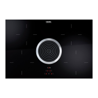
3 2
4 1
Fig. 6.37 Calling up the dealer and service menu
The standard display appears and the fan symbol
pulses for 2 minutes.
Long press on the fan symbol .
4 input points