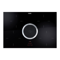
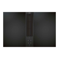
Inserting the cooktop
1
2
Fig. 6.27 Inserting the cooktop
[1] Retaining brackets
[2] Installation clamps
INFO 2 installation claps must be fitted to each side of
the cooktop.
Slide the 4 installation clamps [2] until they reach
the stop position in the retaining brackets [1] on the
bottom of the cooktop
Slide the 4 retaining brackets into the fixtures provided
on the bottom of the cooktop.
54321
Fig. 6.28 Inserting the cooktop
[1] Cooktop
[2] Inlet opening
[3] Air inlet nozzle
[4] Stainless steel grease filter
[5] Worktop cut-out
INFO The BORA window contact switch UFKS is
available as an accessory (including installation
instructions).
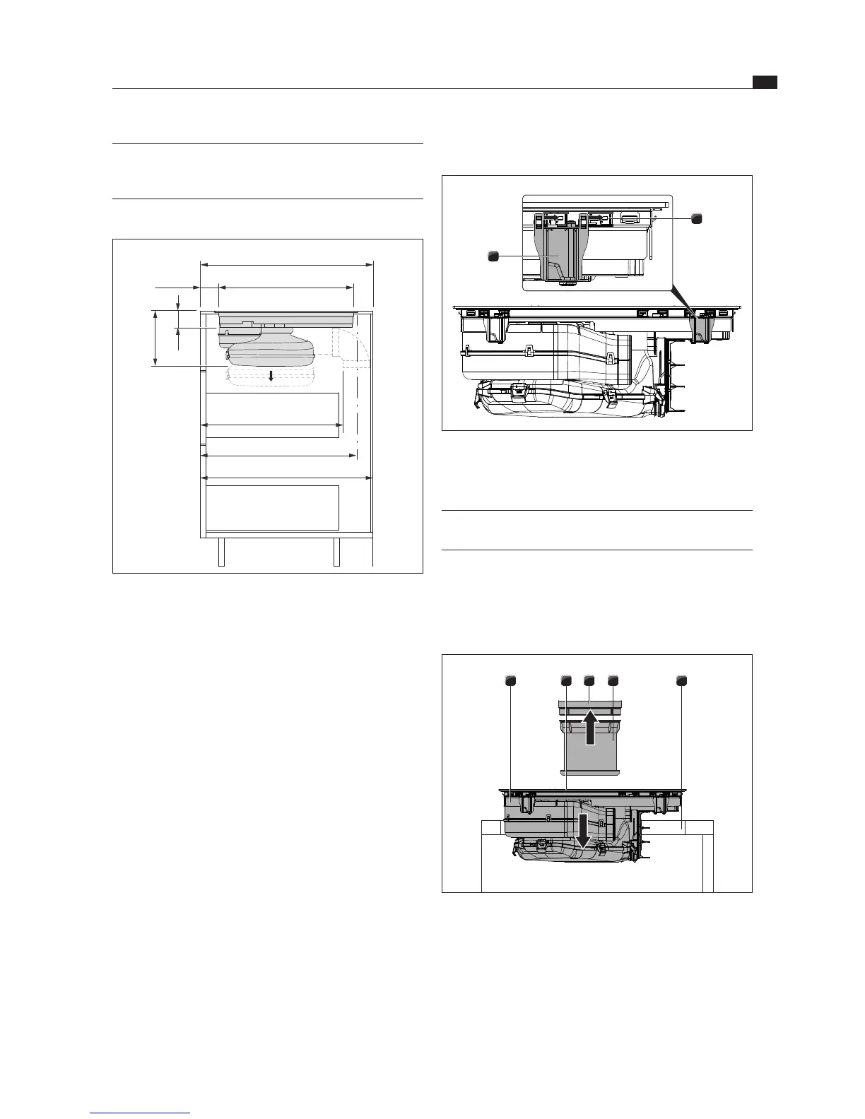
Installation dimensions
530
max. 480
580
68
199
495
min. 600
min. 50
Fig. 6.26 Installation dimensions for exhaust air, worktop depth
600 mm
Installation information
The back wall of the floor unit must be adapted for the
exhaust air duct.
A minimum clearance of 110 mm between the back
furniture body wall and an adjacent kitchen unit or
room wall must be observed for the air duct.
The exhaust air must be directed to the outside by
appropriate exhaust air ducts.
The minimum cross-section of the exhaust air ducts
must be 176 cm
2
. This equates to a cylindrical tube
with a diameter of 150 mm.
The maximum exhaust air duct length is 6 m.
Not compatible with BORA Universal fans.
Planning instructions for the installation of the
exhaust air ducts are provided in the BORA ventilation
handbook.
Preparing the back wall of the kitchen unit
Before installation, check the suitability of floor unit
with regard to the necessary installation dimensions
for the device and the planned duct system.
If necessary, adjust the position of the back wall
according to the required installation dimensions.