Unit Installation
5.2 Minimum Conditioned Room Area
NOTICE
The minimum height of the room (ceiling height) is 7.2 feet
(2.2 m).
Due to the flammable nature of the refrigerant, there are certain
requirements that must be met to employ the use of units with
A2L Refrigerant with charge amount above 62.8oz. If a unit is
connected via a duct system, the total conditioned area must
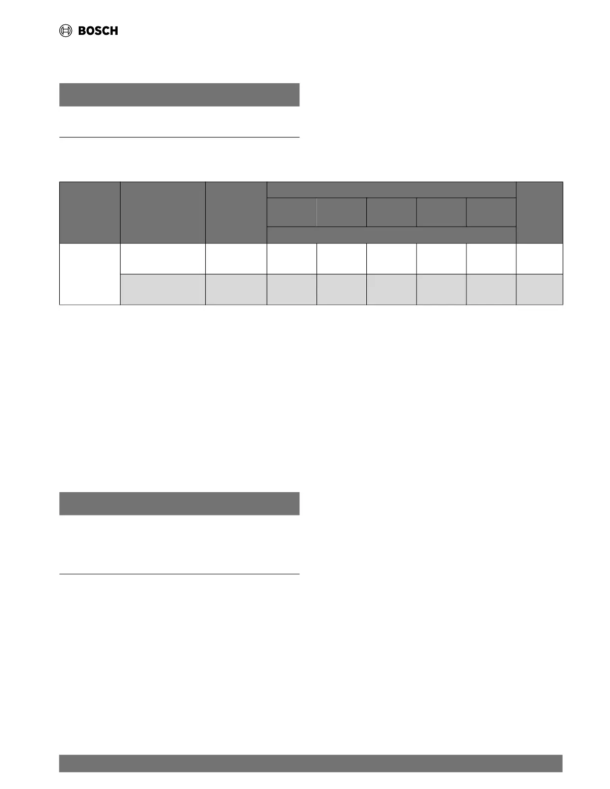
meet the minimum value shown in the table below. This value is
only valid if the minimum airflow (Qmin) requirement is also met.
Refer to the Blower Performance Table to verify airflow values.
(See Table 14 on page #47.)
Table 4 Refrigerant Charge
Model Configuration
Total
Refrigeration
Charge oz.
(kg.)
Ceiling Height
Qmin
CFM
(m
3
/hr)
7.2’
(2.2m)
8’
(2.4m)
9’
(2.7m)
10’
(3.0m)
12’
(3.7m)
Minimum Area of the Total Conditioned Space in ft
2
(m
2
)
CF060
HZ
80
(2.3)
147.5 ft
2
(13.7 m
2
)
133.0 ft
2
(12.4 m
2
)
118.3 ft
2
(11.0 m
2
)
106.4 ft
2
(9.9 m
2
)
88.7 ft
2
(8.2 m
2
)
266
(452)
VT
67.5
(1.9)
124.4 ft
2
(11.6 m
2
)
112.3 ft
2
(10.4 m
2
)
99.8 ft
2
(9.3 m
2
)
89.8 ft
2
(8.3 m
2
)
74.8 ft
2
(7.0 m
2
)
225
(381)
5.3 Protecting the Unit During Construction
Once the unit is properly positioned on the job site, cover it with
either a shipping carton, vinyl film, or an equivalent protective
covering. Cap open ends of pipes stored on the job site. This
precaution is especially important in areas where painting,
plastering, or spraying of fireproof material, etc. is not yet
complete. Foreign material that accumulates within the units can
prevent proper start-up and require costly clean-up operations.
Before installing any of the systems components, be sure to
examine each pipe and all the fitting valves. Remove any dirt or
foreign material found in or on these components.
NOTICE
Equipment should never be used during construction due to
likelihood of wall board dust accumulation in the air coil of the
equipment that permanently affects the performance and
may shorten the life of the equipment.
5.4 Return and Supply Air Duct Flanges Preparation
CF heat pumps feature fold-out return and supply air duct
flanges. These fold-out flanges come folded in from the factory to
allow the heat pumps to more easily fit through doorways and
other tight spaces, and also to prevent damage in shipping and
handling.
Following installation of the heat pump, fold out all fold-out
flanges to
ensure that return and supply air flow is not
obstructed. These flanges can be easily folded using standard or
duckbill pliers. Once folded out, these flanges can be used to
support light duct work loads.
5.5 Mounting Vertical (VT) Units
In order to minimize vibration transmission from the unit to the
building structure mount the CF Series vertical units on a
vibration absorbing pad slightly larger than the unit base. (See
Fig. 2.)
It is generally not necessary to anchor the unit unless required by
local cod
e. All major service access for the CF Series vertical
models is from the front side of the unit. When installing the unit
in a confined space such as a closet, ensure that the service panel
screws are accessible, that the filter can be replaced without
damage, and that water and electrical connections are
accessible. For models with a unit-mounted disconnect switch,
make sure the switch can be easily seen and operated.
To reduce sound transmission, install units using flexible
electrica
l conduit and hose kits. Care should be taken to ensure
that no part of the unit cabinet is touching part of the building
structure.
|
13
CF Series Heat Pumps — 8733846299 (2024/11)




 To Next Page