Unit Installation
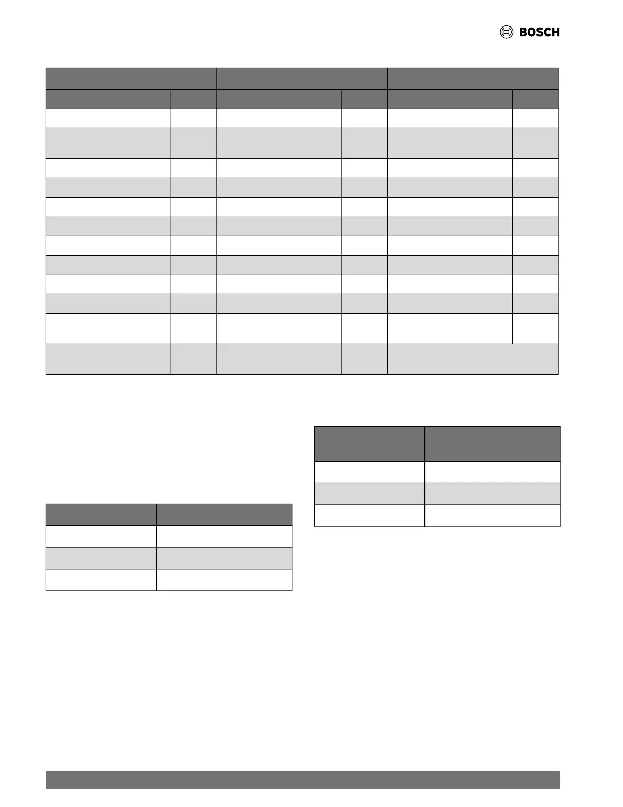
Table 6 Low-Voltage VA Draw —Standard Construction, Hot Gas Reheat or Economizer, and Optional Components
Standard Construction Optional Components Optional Components
Component VA Component VA Component VA
Reversing Valve Solenoid 12 Total VA Draw from “Standard” 27 Compressor Monitor Relay 4
Compressor Contactor Single
Phase
10 Option Card 5 Blower Monitor Relay 4
UPM Board 5 Hot Gas Reheat Solenoid 9 Energy Management Relay 4
Economizer Valve 3 Fire Alarm Relay 4
Heater Relay 10
Aux Relay 10
Heating/Blower Relay 4
5600 DDC 26
EON Board 1
Leaving Water Valve 7
Compressor Contactor
Three Phase
10
Total VA Draw 27 Total VA Draw 44
Total Draw is Dependent on
the Options Installed
5.11.3 Thermostat to HVAC Equipment Wiring
The thermostat may not function properly if the total resistance
of any of th
e thermostat to HVAC equipment wires exceeds 2.5
ohms. To ensure that wire length does not cause excess
resistance, refer to Table 7 and ensure that the wires from the
thermostat to the HVAC equipment are not too long.
Table 7 Length by Wire Gauge for Thermostat to HVAC Equipment
Wiring
Copper Wire Gauge Maximum Wire Length
22 AWG (0,33mm
2
)
150 ft. (46m)
20 AWG (0,50mm
2
)
240 ft. (73m)
18 AWG (0,75mm
2
)
385 ft. (117m)
5.11.4 Remote Sensor to Programmable Thermostat
Because remote temperature sensors measure resistance, very
long cab
le runs can cause slight errors in the measurement. For
the highest temperature reading accuracy, avoid exceeding the
maximum recommended wire lengths show in Table 8.
Table 8 Length by Wire Gauge for Remote Sensor to Programmable
Thermostat Wiring
Copper Wire Gauge Maximum Remote Sensor Wire
Length
22 AWG (0,33mm
2
)
1000 ft. (300m)
20 AWG (0,50mm
2
)
1500 ft. (450m)
18 AWG (0,75mm
2
)
2500 ft. (750m.)
22 |
CF Series Heat Pumps — 8733846299 (2024/11)