D9068 | Operation and Installation Guide | 1.0 Overview
Bosch Security Systems, Inc. | 3/13 | F01U071094-07
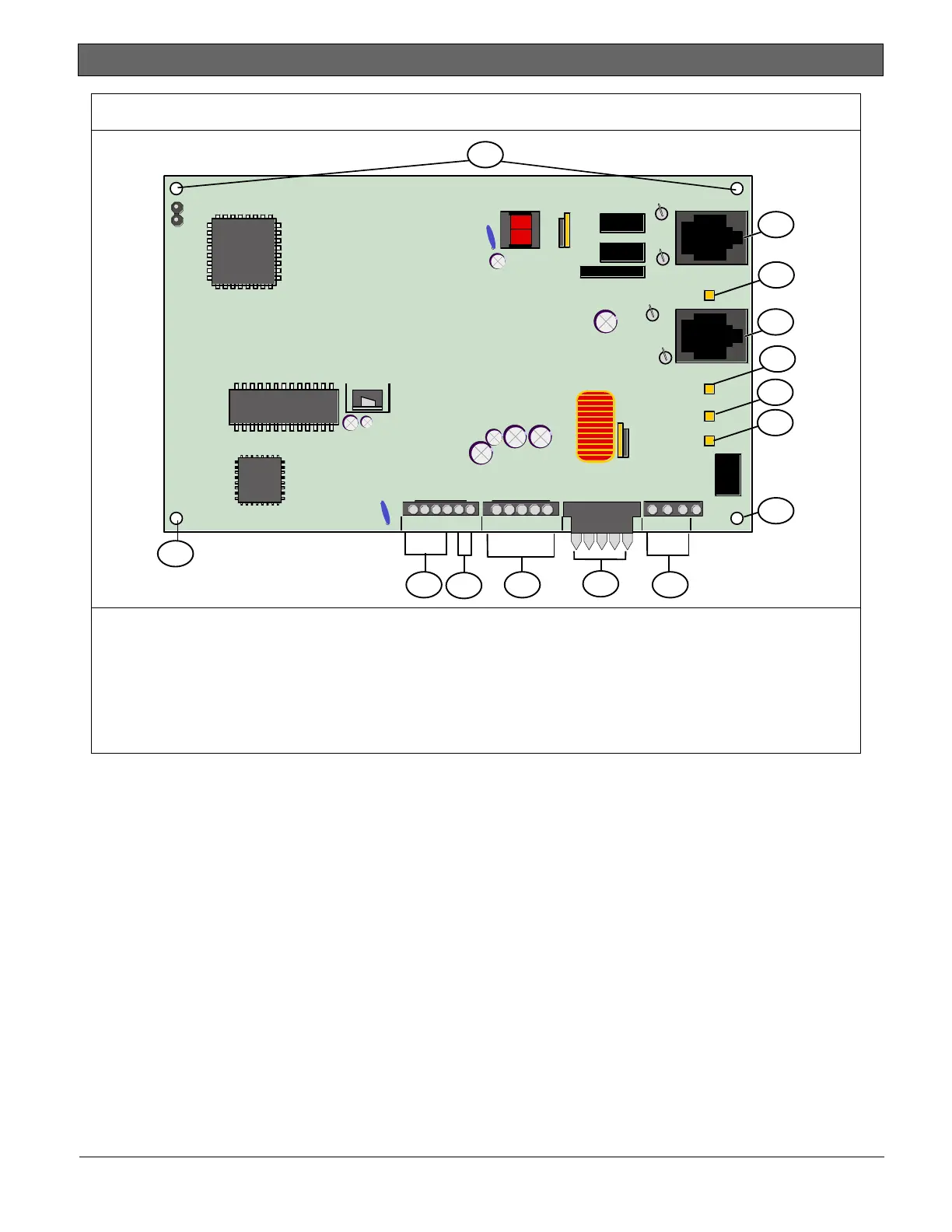
Figure 1: D9068 PCB Layout
LINE 1
LINE 2
+ + - - A B
1 2 3 4 5
NC C NO
SYS TROUBLE
HEARTBEAT
KEYPAD
12
11
10 8
1
3
2
4
5
1*
7
6
9
1
1 - Mounting hole (4)
2 - Phone line 1
3 - Phone line 1 LED
4 - Phone line 2
5 - Phone line 2 LED
6 - System trouble LED
7 - Heartbeat LED
8 - Common trouble relay connector
pins
9 - Keypad Molex connector pins
10 - Input Molex connector pins
11 - Serial connector pins
12 - Power Molex connector pins
* Attach the ground wire at the mounting hole on the lower right corner.